
Choose a Product Series that fits the video requirements and choose a single switch or multiple switches to act as the center of the matrix.
JAP - Plan a New SystemChoose a Product Series MaxColor™ SeriesUltra SeriesOmega SeriesSeries ComparisonChoosing the Right Switch for AMP Standardized SystemsOverviewTraining VideoSupported SwitchesMulti-Switch Considerations for AMP Standardized SystemsOverviewMulti-Switch RequirementsStack vs TrunkBandwidth ConsiderationsSFP+ Cables Supported Inter-Switch ConnectionsSupported SwitchesTraining Video
Choose a Product Series
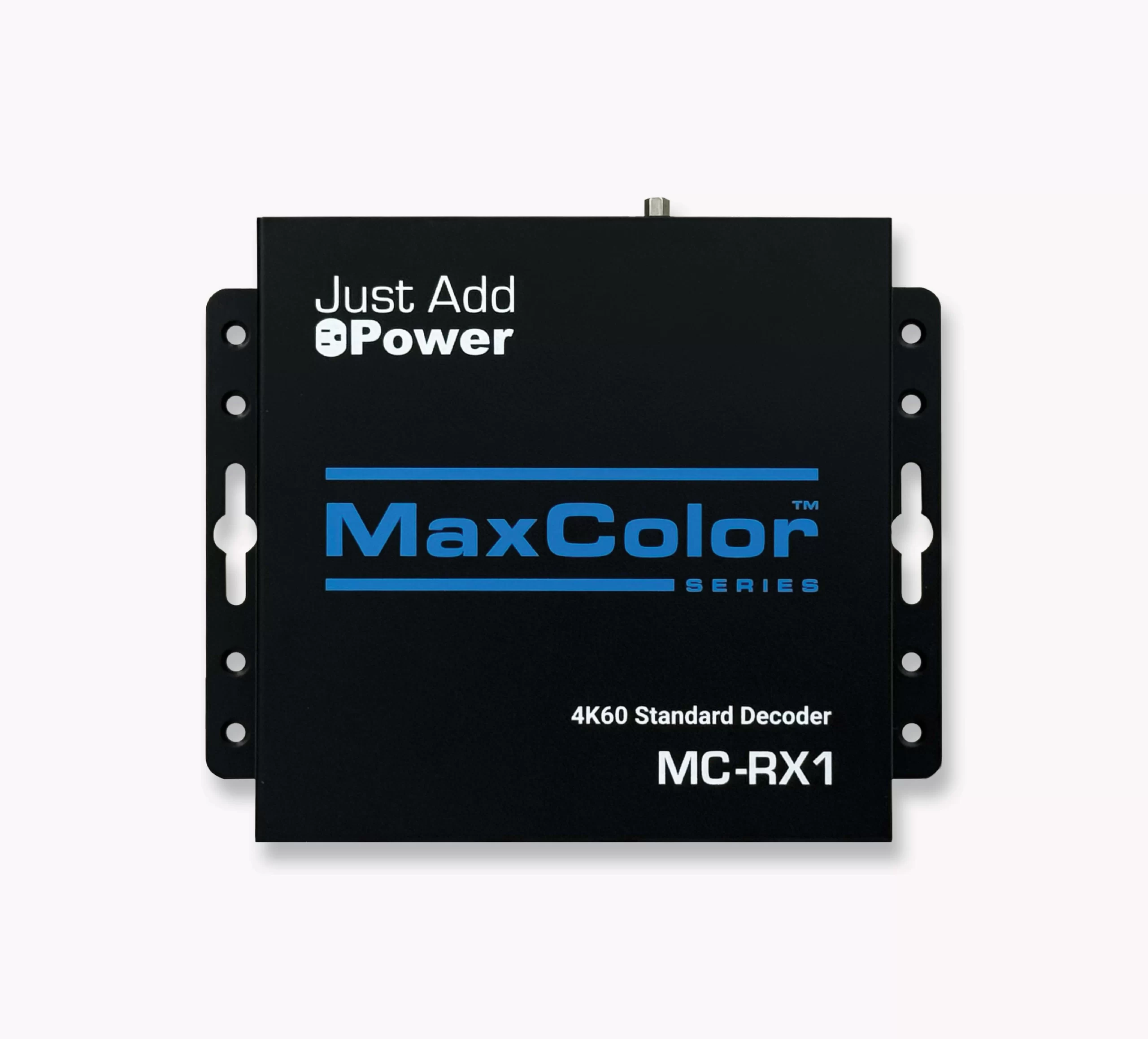
MaxColor™ Series
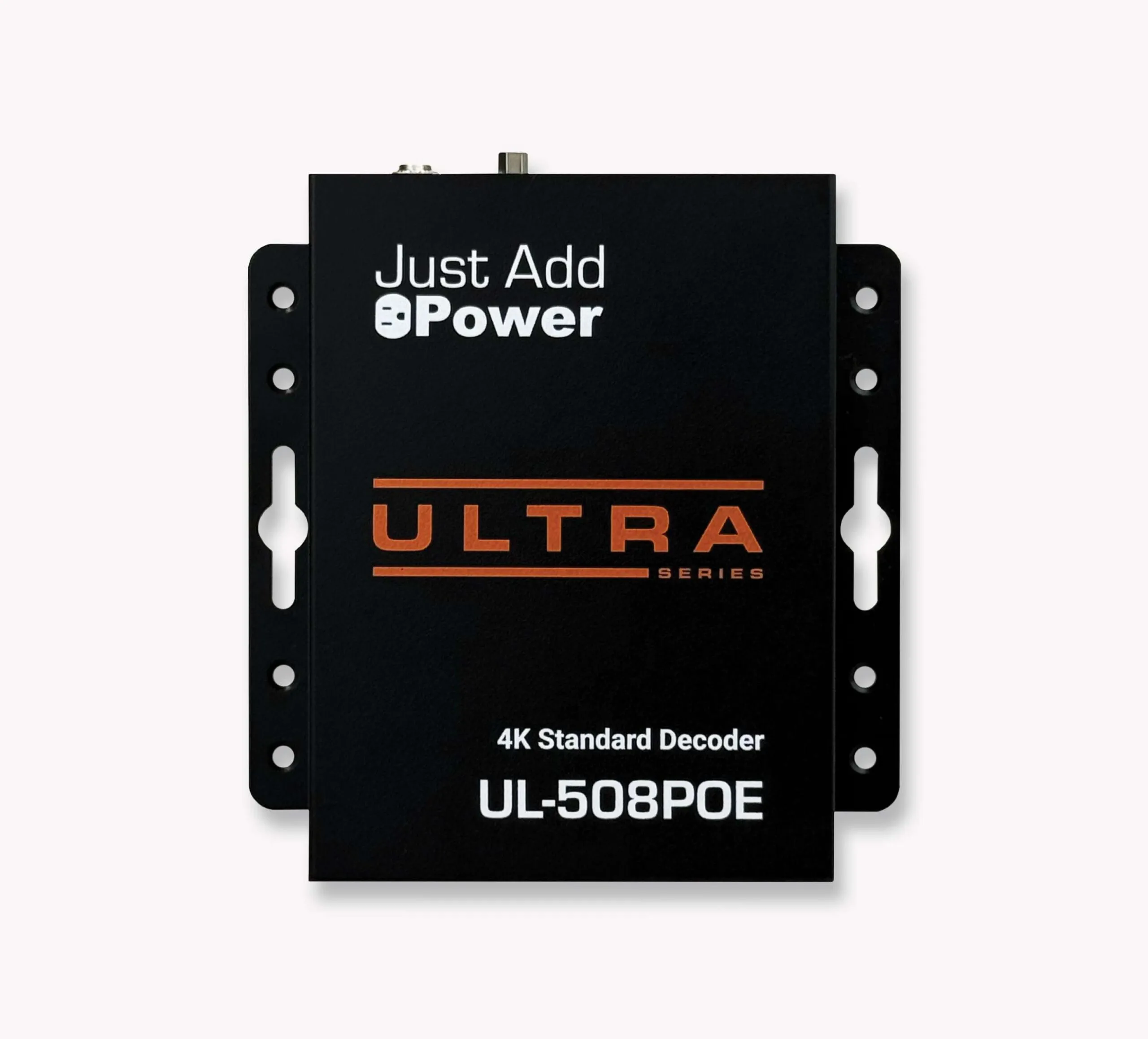
| Ultra Series
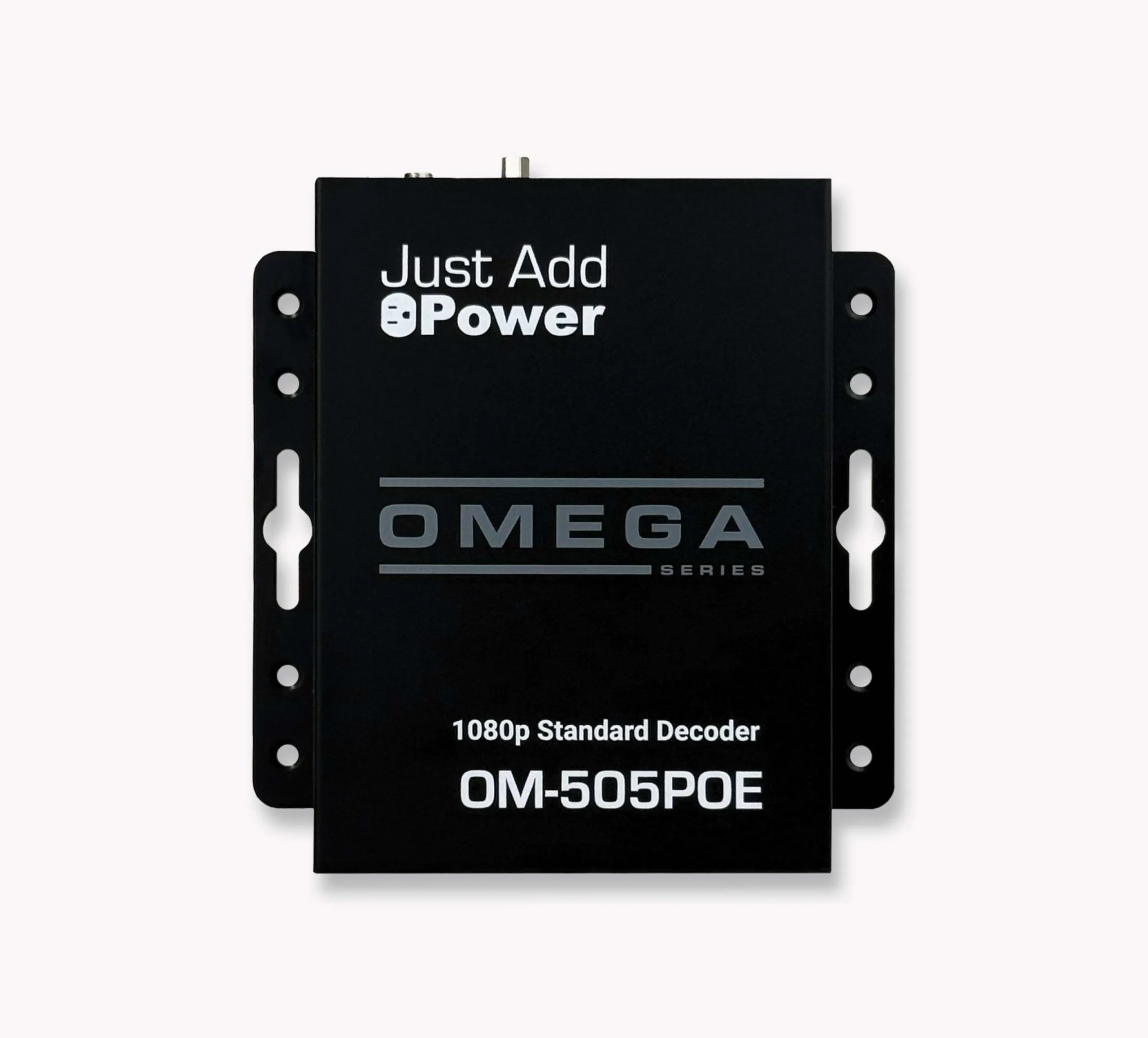
| Omega Series
|
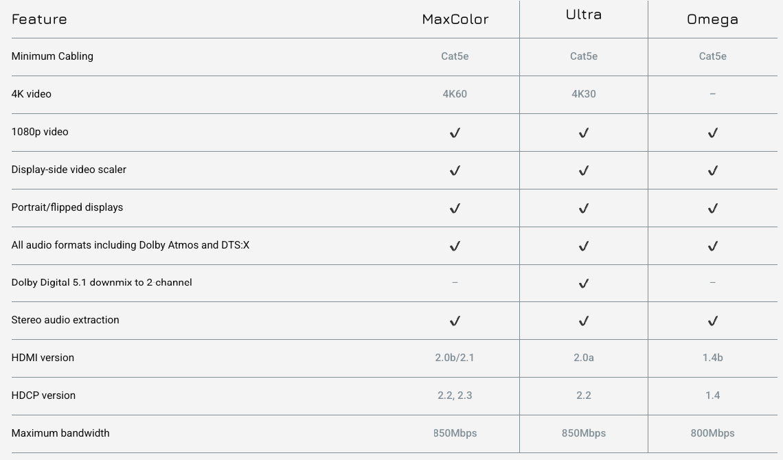
Natively supports 4K@60Hz over 1GbE networks using industry‑standard copper or fiber cabling. | Natively supports 4K@30Hz over 1 GbE networks using industry‑standard cabling (Cat5e or better). | Natively supports 1080@60Hz over industry‑standard cabling (Cat5e or better). |
|
|
|
Series Comparison
Choosing the Right Switch for AMP Standardized Systems
Overview
Building a Standardized Configuration in AMP will fully configure the switches listed below and make them compatible with Just Add Power-provided drivers to support them.
When planning a Standardized System (also known as a VLAN Switching System), one of the most important decisions is the managed gigabit Ethernet switch that is the center of the Just Add Power matrix.
If the Right Switch is too large to fit on one switch or there are multiple switch locations, please see Multi-Switch Considerations for cable recommendations and bandwidth guidelines for systems with multiple switches.
Training Video
Prepare for setting up a system by watching the Standardized AMP Single-Switch Setup video:
Supported Switches
| Model | Devices | POE Watts | POE Devices | Multiple Switches* | Minimum Firmware |
| AMS-1208P | 9 | 130W | 8 | v4.0.6 | |
| AMS-1816P | 17 | 185W | 16 | v4.0.6 | |
| AMS-2624P | 25 | 250W | 24 | v4.0.6 | |
| XMS-1208P | 9 | 130W | 8 | v4.0.6 | |
| XMS-2624P | 25 | 370W | 24 | v4.0.6 | |
| XMS-5248P | 49† | 740W | 48 | v4.0.6 | |
| SW-505-8P-F | 9 | 130W | 8 | v1.00.361 | |
| SW-505-8P-R | 9 | 130W | 8 | v1.00.361 | |
| SW-505-16P-R | 17 | 185W | 16 | v1.00.361 | |
| SW-505-24P-F | 25 | 370W | 24 | v1.00.361 | |
| SW-505-24P-R | 25 | 250W | 24 | v1.00.361 | |
| SW-510-48P-F | 47 | 740W | 47 | v1.0.3 | |
| SW-515-48P-F | 47 | 740W | 47 | v1.00.361 | |
| AMS-4424P | 24 | 250W | 24 | Yes | v4.0.6 |
| XMS-7048P | 49† | 740W | 48 | Yes | v4.0.6 |
| SW-610-24P-R | 24 | 370W | 24 | Yes | v1.0.3 |
| SW-610-48P-F | 48 | 740W | 48 | Yes | v1.0.3 |
| SW-615-24P-R | 24 | 370W | 24 | Yes | v1.00.361 |
| SW-615-48P-F | 48 | 740W | 48 | Yes | v1.00.361 |
*To use multiple switches in the same system, the switches must have 10Gb ports. Additionally, all switches MUST be from the same manufacturer, but may be different models.
†Maximum of 48 Receivers on a single switch. The 49th device can only be a Transmitter.
Multi-Switch Considerations for AMP Standardized Systems
Overview
If the Right Switch for a Standardized System (also known as a VLAN Switching System) requires more than one switch, AMP supports up to 63 switches in a single system.
Before You Begin: Multi-switch AMP Standardized systems require switches from the same manufacturer, 10Gb SFP+ interconnects, and sufficient uplink bandwidth between switches. Verify switch compatibility and bandwidth requirements before designing the system.
Multi-Switch Requirements
- All switches must be from the same manufacturer.
- All switches must include 10Gb SFP+ ports.
- Switches must be interconnected using supported SFP+ modules or DAC cables.
- AMP uses trunk links and link aggregation groups (LAGs) between switches.
- Switch 1 reserves its final port for network access.
- Sufficient PoE capacity must be available for all connected devices.
Stack vs Trunk
AMP Standardized Configuration supports multi-switch systems in trunk topology.
Please see Stacking vs Trunking for more information.
Bandwidth Considerations
When designing a multi-switch AMP Standardized system, sufficient bandwidth must be available between switches to carry video traffic across inter-switch links.
The table below shows the typical bandwidth characteristics of each Just Add Power product family. This information may be useful when evaluating switch models and available uplink capacity.
| Generation | Average Bandwidth* | Recommended Encoders per Gb |
| Omega | 300 Mbps | 3 |
| Ultra | 500 Mbps | 2 |
| MaxColor | 850 Mbps | 1 |
*Actual bandwidth will depend on source resolution, framerate, colorspace and content. The peak bandwidth output of an Omega or Ultra Encoder is 850 Mbps, most often during boot-up and source switching. The peak bandwidth output of a MaxColor Encoder is also 850 Mbps.
The number of SFP+ ports on each switch, combined with the number of switches in the system, determines how many SFP+ links can be created between switches. Standardized Configuration builds a system so that half of the SFP+ ports connect to one switch, and the other half connect to another switch. This lets switches link together in a chain topology.
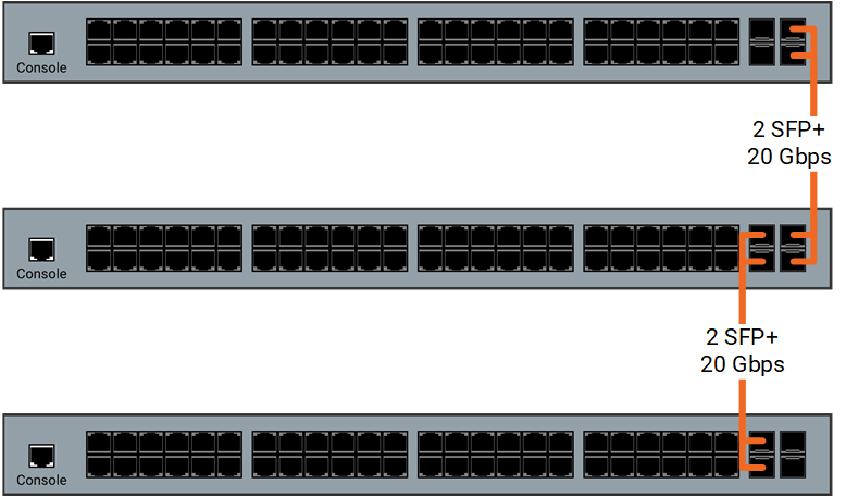
SFP+ Cables
Connecting multiple switches together requires a specialized cable, and cannot be carried over typical CatX wiring.
Most SFP+ cables are compatible, regardless of the manufacturer.
Supported Inter-Switch Connections
- Direct Attach Copper (DAC) cables
- Fiber optic cabling with SFP+ transceivers
- Compatible third-party SFP+ modules
Note: AMP Standardized multi-switch systems require 10Gb SFP+ inter-switch connections. Standard 1Gb RJ45 switch ports cannot be used as inter-switch uplinks.
Supported Switches
| Model | Devices per switch | POE Devices | POE Watts | SFP+ Ports | Minimum Firmware |
| AMS-4424P | 24 | 24 | 250W | 2 | v4.0.6 |
| XMS-7048P | 49† | 48 | 740W | 2 | v4.0.6 |
| SW-610-24P-R | 24 | 24 | 370W | 4 | v1.0.3 |
| SW-610-48P-F | 48 | 48 | 740W | 4 | v1.0.3 |
| SW-615-24P-R | 24 | 24 | 370W | 4 | v1.00.361 |
| SW-615-48P-F | 48 | 48 | 740W | 4 | v1.00.361 |
†Maximum of 48 Decoders on a single switch. The 49th device can only be a Encoder.
Training Video
Prepare for setting up a system by watching the Standardized AMP Multi-Switch Setup video: