
The goal of this document is to help you optimize your wireless network to avoid the most common Wi-Fi issues, such as devices falling off the network, roaming issues, and video calling issues. Recommended radio power levels have changed over time because the data needs of devices have changed over time.
Wi-Fi Best PracticesBackgroundMethodologyWhy are we focusing on the 6 GHz band first?Wireless considerations for project designConsider site survey toolsWireless antennasWi-Fi standards (n/ac/ax)Building materialsBest practices for setting an AP's power levelCreate a starting pointWouldn't maximum power give me more coverage and range?Adjusting the Transmit PowerHow to perform a Site SurveyUnits of measurementSurveying the signal strength from AP to APSurveying the signal strength from the AP to the client deviceWhy these values?Wi-Fi channel optimizationGeneral guidelines for channel selection5GHz band2.4GHz bandWorking around Zigbee channelsChannel widthUnderstanding real-world Wi-Fi throughputSo, what is realistic?Wi-Fi feature recommendations802.11r Fast Roaming / Fast TransitionBand SteeringMulticast EnhancementRSSI Threshold / Client RejectMAC Address FilteringSpanning Tree Protocol (STP)Installing Wi-Fi 7What does Wi-Fi 7 add?Wi-Fi 7 requirementsExpectations and deploymentMixing Wi-Fi 5, 6, and 7
Background
Since wireless data needs have evolved, so must our wireless deployments. We used to worry only about providing an adequate signal to our devices. Now, we also need to ensure that every device can transmit data at the proper rate to satisfy the more demanding applications people use every day. This means using more APs, closer together, with lower radio power.
Methodology
During testing, segregate the bands by creating unique 2.4 , 5, and 6 GHz SSIDs so you know which band you’re connected to. Optimize the 6 GHz band first, then 5, and 2.4 GHz last. Test each band individually to ensure you have complete coverage.
If you're using 6GHz, you may need to turn 2.4 GHz off on some access points to avoid signal overlap.
Why are we focusing on the 6 GHz band first?
The 6 GHz band allows for faster data transfer rates and more channel selection options to allow for less interference. The trade-off is that it does not have a large range, so you'll need more access points for full coverage. If a device is 6 GHz capable, you want it connected to the 6 GHz band. The chart below illustrates why.
| 2.4 GHz | 5 Ghz | 6 GHz | |
| Operating Distance | Travels farther | Less range | Even less range |
| Interference | Very high | Low | Very low |
| Barriers | Less signal loss | More signal loss | Even more signal loss |
Wireless considerations for project design
There are three major factors to consider when designing a Wi-Fi project:
- Wireless antennas
- Wireless standards
- Building materials and environmental interference
Wireless antennas and standards exist in APs and client devices, with the lowest common denominator determining the maximum speed. Building materials and environmental RF interference must be considered as well, as most advertised Wi-Fi speeds were tested in a non-congested space with a clear line of sight between the AP and client device. Read Understanding real-world Wi-Fi throughput to learn more.
Consider site survey tools
MetaGeek’s Wi-Fi surveying and troubleshooting tools make Wi-Fi deployments easier. Tools such as Tamograph allow you to build a heatmap of the site, so you have a good idea of where the APs should be placed before rolling a truck. MetaGeek’s Wireless Spectrum Analyzer can help you identify environmental factors affecting Wi-Fi speeds, such as Bluetooth devices, Zigbee broadcasts, and other forms of RF interference.
Wireless antennas
Antenna configurations (2×2, 3×3, 4×4) determine the maximum capacity of the device, as shown in the table below.
| Antenna Configuration | Max Speed for 802.11n (2.4 and 5 GHz) | Max Speed for 802.11ac (5 GHz) |
| 1×1 | 150 Mbps | 433 Mbps |
| 2×2 | 300 Mbps | 866 Mbps |
| 3×3 | 450 Mbps | 1300 Mbps |
| 4×4 | 600 Mbps | 1733 Mbps |
Note: These are the maximum speeds reached in lab environments and are rarely achieved in real-world situations. See Understanding Real-World Throughput for more information.
Client devices also have antenna configurations, and the smallest antenna configuration determines the maximum throughput. If a 2×2 device connects to an AP with a 4×4 configuration, it’s considered a 2×2 connection, and the maximum possible speed is 866 Mbps using 5 GHz. The same applies if the mobile device has a 4×4 configuration and the AP has 2×2. Most mobile devices have a 2×2 configuration.
Wi-Fi standards (n/ac/ax)
802.11n, ac, and ax are Wi-Fi standards that have progressively increased the data transfer rates our devices are capable of. You may have seen them referred to as Wi-Fi 5 (ac) or Wi-Fi 6 (ax). What’s important to understand is that these standards are backward compatible, but that doesn’t mean that a Wi-Fi 6 device is going to make a Wi-Fi 5 AP faster.
Example: You installed an Araknis 810 Series AP for a customer, but they’re only seeing about 85 Mbps on their smart TV. The Araknis AP has a 4×4 antenna configuration and is ac compatible.
Check the Smart TV’s specs. Odds are it uses an older 802.11n chipset which immediately brings the maximum speed down. Even with a 2×2 antenna configuration, there’s a Bluetooth soundbar and subwoofer in that room, and a brick fireplace between the TV and AP.
Checking the specifications of the client device you’re running a speed test from is an important—and commonly missed—troubleshooting step.
Building materials
Keep building materials in mind when placing APs throughout a site. Below is a chart of common building materials and the expected amount of signal loss they create.
| Material | Signal Loss |
| Hollow wood door | 4 dBm |
| Drywall | 3 dBm |
| Brick | 6 dBm |
| Concrete | 8-15 dBm |
| Refrigerator | 19 dBm |
Best practices for setting an AP's power level
Follow these best practices to quickly optimize your AP broadcasts.
Create a starting point
Adjust the power levels on all APs to Low (13 dBm) on the 2.4 GHz radios, Medium (18 dBm) on the 5 GHz radios, and 60 dBm for 6 GHz.
Wouldn't maximum power give me more coverage and range?
Think about it this way. An AP has radios with adjustable power levels. A client device has radios with fixed power. At a lower AP radio power level, you can match the distance of the signal range between the AP and the client device. This means using more APs, closer together, with lower radio power.
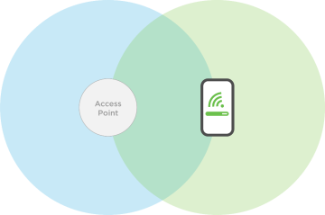
This allows you to maintain a consistent data transfer rate between an AP and client device.
If you increase the AP’s radio power, the AP could have a longer transmit range than the device.
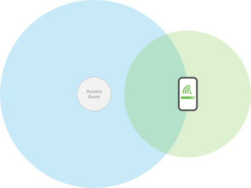
With this signal gap, the client device may not be able to connect to the AP. If you are able to maintain a signal, you have a decreased data transfer rate, allowing you to perform less-demanding tasks like email or web browsing. With more demanding tasks like Wi-Fi calling and video calls, you start to see issues like dropped calls or spotty connections.
Adjusting the Transmit Power
If possible, avoid any changes to the AP radio power levels described in the Creating a Starting Point.
Physically move the APs closer or further apart until the AP-to-device measurement meets the target values. If you must adjust the transmit power, do not increase or decrease more than 3 dBm from the starting point. Adjusting the power level more than 3 dBm runs the risk of the AP’s signal range being higher than the client device’s, or providing too weak a signal to provide useable data throughput.
The lower you set the AP’s power level, the less throughput you’re able to achieve at greater distances. It is not recommended to lower your power levels below 10dBm, which most manufacturers don’t allow, anyway. If you find you need to reduce radio power to 10 dBm (2.4 GHz) and 15 dBm (5 GHz) or lower, you either need to remove an AP or rethink AP placement.
How to perform a Site Survey
Create separate SSIDs for the 2.4, 5, and 6 GHz bands while performing a site survey. This makes it easy to know where you’re at while testing.
Once the site survey is complete, we recommend giving both SSIDs the same name to make it easier for the customer to use. This avoids confusion and potential Technical Support calls. (SSIDs can use the same name without interfering with network communications.)
If you, or the customer, decide to keep them separate, make sure the customer knows the difference between the two SSIDs.
Pro Tip: Do not permanently mount devices until the site survey is complete.
There are 2 parts to performing a proper Wireless Site Survey:
- Surveying the Signal Strength from AP to AP
This helps you approximate the proper mounting locations for the APs in your system. - Surveying the Signal Strength from AP to Client Device
This is the most important value. Do your best to keep this signal from getting too weak so you have enough signal to maintain high bandwidth data transfers from the client device to the AP.
Units of measurement
Signal strength can be measured one of two ways: RSSI (received signal strength indicator) or dBm. Depending on the application being used, it’s good to know how these units of measurement differ.
- RSSI is a relative unit of measurement that depends on the device’s Wi-Fi card.
- dBM is an absolute unit of measurement, using mW (milliwatts).
Wi-Fi signal strength is measured in signal loss, meaning that the value is a negative number. The closer you are to zero the better, though you’ll rarely see a measurement better than -30.
Surveying the signal strength from AP to AP
Most APs typically provide a feature to scan the surrounding area for other APs. For specifics on the feature, see the AP’s user manual. Below are the basics to finding approximate mounting locations for your APs.
Place the first and second APs in temporary locations, then perform a scan from the first AP.
The next AP should be at an RSSI of between -65 and -70 dBm. Move the second AP closer if the signal between them is too weak, and further away if the signal is too strong. This should put the APs at a rough distance that provides adequate signal to a client device that is between them, which is why we’ll be surveying the signal from the AP to the client device next, using a Wi-Fi analyzer app.
Note: APs have much stronger radios than a client device does, so -70 dBm from AP to AP is much different than -70 dBm from AP to client device. The target range of -65 and -70 can be debated, but this range is what our support team finds most helpful to find an approximate AP location. Surveying the signal from AP to client device gives you more defined values for final placement.
Surveying the signal strength from the AP to the client device
Install a Wi-Fi analyzer app on your device. A quick search for “Wi-Fi analyzer” in the Google Play Store provides plenty of options. For iOS, use their AirPort Utility app. We’ve partnered with MetaGeek for their Wi-Fi tools that include a spectacular Wi-Fi analyzer, which measures in dBm.
A Wi-Fi analyzer app displays the wireless signal strength from all the APs broadcasting in your area. The results that are displayed are very similar to the results seen in the scans done in the AP but are provided in real time, and adjust as you move with the device running the analyzer app.
In a multiple-AP deployment, stand directly between the two APs with the Wi-Fi analyzer app running. The target values are:
- 6 & 5 GHz Target of -65 (RSSI or dBm)
- 2.4 GHz Target of -70 (RSSI or dBm)
Note: The unit of measurement depends on the application being used.
Maintaining these target values between APs ensures you’re not losing too much signal from the AP, resulting in a strong Wi-Fi connection and consistent data transfer rate. For this reason, you want to make sure that your 5 GHz device never falls below this value at any point in the system.
Why these values?
Client device manufacturers typically set their roaming threshold to about -65 through -70 dBm. For this reason, we suggest a 5 GHz target of -65 dBm to account for the most sensitive devices.
You may have noticed that the 2.4 GHz target is lower. This is for a few reasons:
- 2.4GHz devices do not typically require high data transfer rates.
- If a device does require high data transfer rates, it can most likely use a 5GHz connection.
- Devices prefer the strongest signal they see.
- If the 2.4 GHz RSSI is weaker than the 5 GHz RSSI at the roaming point between APs, the 5 GHz signal is always preferred.
Note: Roaming behavior is dependent on the client device manufacturer. Some devices prefer a 5GHz signal, some look for the strongest signal available and may move between 2.4 and 5GHz. Not all devices are 5 GHz capable, so we need to accommodate those devices, as well.
Wi-Fi channel optimization
The goal is to place the APs on channels as far apart from each other as possible. Manually placing each AP on a channel makes sure the APs placed in the system aren’t interfering with each other.
Perform a Site Survey to see what channel the APs are broadcasting on. Most APs have an auto-channel feature that looks for the least-congested radio channel in the area on startup, but it is not perfect. The AP checks the channels only at time of startup, so if there are multiple APs on site, the channels can quickly change. Also, other devices on site may not currently be turned on and broadcasting their RF signals. Read How to perform a Site Survey for more information.
Example: In a two-AP system, place one AP on channel 36 on the 5 GHz band, and the other on channel 165. Remember to use site survey tools, such as a spectrum analyzer, to see if the channels you’re placing the AP on aren’t already congested with interference from a neighbor’s AP or other devices in the environment.
General guidelines for channel selection
5GHz band
- Use non-DFS channels (36-48 and 149-165).
- When using one or two APs, an 80 MHz channel width is acceptable if your site survey does not show a congested 5 GHz band.
- If using three or more APs, a 40 MHz channel width is recommended. This has less throughput potential but creates a 5 GHz network that isn’t as susceptible to interference.
Note: DFS channels are reserved for government radar systems, and not all devices can connect to them. If you use a DFS channel for your AP, it may be booted to another channel, interfering with the customer’s Wi-Fi system.
2.4GHz band
- Use channels 1, 6, and 11.
- Do not use a channel width of 40 MHz.
- A Wi-Fi router or access point co-located with a mesh controller can overpower all Zigbee communication to that controller, even if the channels are not overlapping. Always move the AP at least 5 meters (15 feet) away from the mesh controller.
The 2.4 GHz band allows the use of channels 1-11, but Wi-Fi is typically constrained to channels 1, 6, and 11. These channels are chosen because they allow the most amount of separation from each other. While you could use channels 2 and 9 in a two-AP system, odds are you’re going to cause massive amounts of interference with the neighbors, and vice versa.
Working around Zigbee channels
The Zigbee standard defines 15 channels, all within the 2.4 GHz radio band. Because Wi-Fi shares this band with Zigbee and can easily interfere with it, you must plan Zigbee channels to work alongside Wi-Fi channels without interference. Zigbee channels are numbered 11-25, but they overlap many of the same frequencies as Wi-Fi channels 1-11. Zigbee channels are narrow (2 MHz wide), while Wi-Fi channels are wide (22 MHz), so a single Wi-Fi channel can interfere with multiple Zigbee channels.
Channel width
Increasing channel width decreases the number of available channels by combining them. This increases potential throughput, but also increases the likelihood of interference.
As you can see by the image below, using anything more than 20 MHz on a 2.4 GHz band greatly increases the risk for interference and is strongly discouraged.
5 GHz has many more channels available, allowing the possibility of widening the channel. It’s not recommended to go above 80 MHz, because it interferes with DFS channels. Going below 40 MHz decreases the potential throughput.
Our recommendation is to use 80 MHz if the system has two APs, and 40 MHz if using three or more. There are exceptions, but it’s best to use proper site survey tools before using three or more APs with 80 MHz channels. This increases the risk of the APs interfering with each other or getting interference from other devices in the environment.
Understanding real-world Wi-Fi throughput
There are two facts we can't ignore:
- Internet Service Providers (ISPs) have increased their speed offerings to consumers.
- Consumers’ expectations have increased dramatically when it comes to their Wi-Fi experience.
Almost every major networking equipment manufacturer has a product that boasts phenomenal Wi-Fi speeds: “1200 Mbps,” “1750 Mbps,” or “come here for 2600 Mbps!” But when the integrator sells those Wi-Fi speeds to the consumer, reality hits after deployment. Speeds are not near what has been advertised, dead spots still exist, and buffering is the kiss of death when the consumer paid for full-gigabyte service from the ISP.
Networking equipment manufacturers (ourselves included) have fallen into what we call "the numbers game." Let's take a 3×3 Wireless AC access point, for example:
The advertised speed for this product is 1750 Mbps. Pretty great when you have 450 Mbps coming from the ISP, right? Before you get excited, let's break down how manufacturers got the 1750 Mbps number. The math is simple: we have 3 streams on 2.4 GHz and 3 streams on 5 GHz radio interfaces.
Per 802.11ac standards, on 2.4 GHz radio, when a device establishes a connection with the access point using 40 MHz channel bonding (MCS7), then the stream maximum throughput is 150 Mbps. We have 3 streams on 2.4 GHz, which equals 450 Mbps on the 2.4 GHz radio.
Similarly (again per 802.11ac standard), when a device establishes a connection with the access point using a 5 GHz radio and 80 MHz channel bonding (MCS9), then the stream maximum throughput is 433.3 Mbps (5 GHz has more throughput than 2.4 GHz). We have 3 streams on 5 GHz, as well, equaling 1300 Mbps on 5 GHz.
Now, since the access point is dual-band concurrent, combine the maximum speeds on both interfaces and voila! We have 450 Mbps + 1300 Mbps = 1750 Mbps!
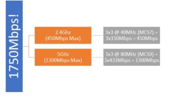
Because that graphic makes it much simpler to understand…
The main problem with this math—while technically correct—is that it's not realistic.
So, what is realistic?
Starting with 2.4 GHz interface, since the spectrum is very congested and the number of non-overlapping channels on the 2.4 GHz spectrum is limited to 3 channels, each of which is 20 MHz wide, there are no devices that negotiate 40 MHz channel bonding on 2.4 GHz. The probability of frame retransmissions is very high when using 40 MHz on a 2.4 GHz radio due to noise or interference. So, achieving 40 MHz channel bonding on 2.4 GHz—while technically possible and tested in labs—is virtually impossible in real life. Devices opt for 20 MHz channel bonding only, which results in the case of 3 streams to a maximum of 195 Mbps (remember it was 450 Mbps in the ideal state).In addition, Wi-Fi as a technology is a shared medium. In other words, it's a half-duplex medium. Only one device can talk at any one point in time: either the access point to a client device or a client device to the access point. This means the maximum 195 Mbps is effectively a maximum of 97 Mbps realized by the client device (it must listen half of the time, assuming no one else is “talking” to the access point).
The fun doesn't stop here—this 97 Mbps assumes the wireless medium is used 100% of time to transmit content (for example, a YouTube video stream), but that's not the case. Since it's a shared medium, Wi-Fi is notorious for having management traffic overhead in order to control who is talking at one point of time and who gets to talk next. This management overhead increases dramatically by three factors:
- Number of SSIDs advertised on an access point.
- Number of access points in the location.
- Number of Wi-Fi devices in the location.
The more of these three factors, the more coordination and management messages need to be sent, occupying valuable airtime that could be used to transmit actual traffic. Also, interference causes faulty frames to be received, which triggers retransmissions and slows down mechanisms, lowering the effective throughput.
In addition, the maximum throughput assumes you have a clear line of sight and a very little distance between the device and the access point. The further the client device moves away from the access point, the weaker you’re the signal, and the lower the throughput. The same logic and limitations go to 5 GHz radio.
So, what does that mean to the effective real-life throughput? In order to answer that, we have to flip the perspective of the above figure to be from the client device trying to connect to an access point. All the aspects listed below dramatically affect the throughput of the device:
- Radio Interface: Big difference between 2.4 GHz and 5 GHz from a nominal speed perspective.
- Number of streams: It's a two-way street between the device and the access point. Most mobile devices have only two streams.
- Channel Bonding: If the radio interface is 2.4 GHz, 20 MHz is the realistic channel bandwidth. If 5 GHz, we start with 80 MHz but can automatically fall back to 40 MHz if the environment is noisy.
- Half-Duplex Nature: By design, Wi-Fi is half-duplex, so whatever the maximum negotiated throughput, it's cut in half because of this.
- Wi-Fi Overhead: The more access points and SSIDs at a location, the less effective the wireless medium is.
- Wireless Contention: The more Wi-Fi devices trying to connect to an access point, the longer a certain device waits before it gets a chance to talk.
- Distance from the AP: Also known as signal strength, which degrades naturally with distance as well as obstacles near the location.
- Interference: All sources of interference severely affect the effective throughput.
- Legacy Devices: Because of the half-duplex nature, if there is an old device talking at 54 Mbps on the network, all other devices will wait longer for the old device to finish talking.
- TCP Acknowledgements: If the connection is TCP, it adds a lot of overhead to the medium because every packet needs to be acknowledged by the receiver.
- Retransmits: If one bit of a frame is corrupted due to collision, the entire frame needs to be retransmitted.
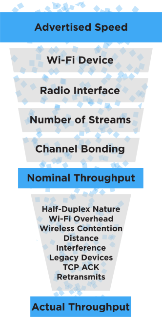
These factors subtract from the nominal throughput and vary widely by each location or time frame. This results in rules-of-thumb throughput figures rather than concrete numbers (more of an average than a measurement). We find that a good 2.4 GHz environment provides an effective throughput between 20 Mbps-40 Mbps, while a good 5 GHz environment provides 150 Mbps-400 Mbps effective throughput. These are big deltas from the advertised maximum theoretical numbers by networking equipment manufacturers, which are, again, technically not wrong.
So, the next time a customer asks you, “I just signed up for 300 Mbps internet; will I get 300 Mbps across the house via Wi-Fi?" The answer is: technically yes, but realistically not likely.
Wi-Fi feature recommendations
Unless you have a specific use case, we do not recommend the following features.
802.11r Fast Roaming / Fast Transition
This feature is designed to help client devices transition between access points when moving across the site. Keep in mind that devices that do not support this protocol may not connect or may intermittently lose connection. Disable Fast Roaming as a troubleshooting step if a device refuses to connect.
Band Steering
There’s no industry standard for band steering, so AP and client device manufacturers implement it differently, causing communication issues.
Multicast Enhancement
This setting converts multicast traffic from the LAN to unicast traffic when transmitted to wireless. It is meant to improve multicast communication over a wireless connection, but it can create issues for multicast communication.
RSSI Threshold / Client Reject
This sets an RSSI cutoff that disconnects devices when they reach the set value.
Example: You set a cutoff value that causes the AP to disconnect devices at 80% of the AP’s maximum transmit power. The client device doesn’t understand why it disconnected and can potentially get stuck in a loop trying to reconnect. The customer perceives this as a Wi-Fi issue, and it’s going to drain the client device’s battery.
MAC Address Filtering
MAC filtering typically creates a problem when configured from an AP. If you need to keep a device off the network, check the router’s manual to see if it has a MAC filtering feature.
Example: The AP has a client device’s MAC address listed in the MAC filtering table. The client device doesn’t know this and continues to try and connect, which can result in a loop. The customer perceives this as a Wi-Fi issue, and it’s going to drain the client device’s battery.
Spanning Tree Protocol (STP)
Typically configured on network switches. The use case for an AP is extremely rare.
Installing Wi-Fi 7
Before you deploy Wi-Fi 7, there's some information you'll want to know to set your customers' expectations and deliver a successful deployment.
What does Wi-Fi 7 add?
- 6 GHz expansion for a cleaner spectrum that doesn’t support legacy devices.
- 320 MHz doubles the channel width for higher throughput in low-interference environments.
- WPA3 encryption. 6 GHz does not support WPA2.
- 4K-QAM increases data density by almost 20% compared to 1024-QAM, at strong signal levels.
- Multi-Link Operation (MLO) enables a client device to use multiple bands simultaneously. This provides a more reliable connection and lower latency. This requires the client device to support MLO.
- Standard Power provides a higher 6 GHz transmit power in supported regulatory domains.
- Multi-gig edge expectations with a strong signal.
Note: MLO and Standard Power are coming soon to the AN-x30 series access points.
Wi-Fi 7 requirements
- Multi-gig switching at 2.5 Gbps+. Clients won’t notice the speed without a 2.5 Gbps internet service, a 2.5 Gbps modem, router, and switch.
- Cat6/6A cables. 6A is required for 10 Gbps.
- A PoE (802.3bt) budget that supports 60W per AP.
- Client devices that support Wi-Fi 6E/7.
Expectations and deployment
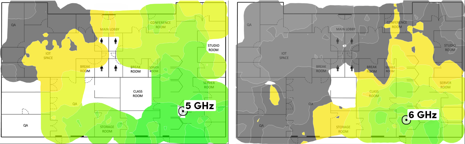
6 GHz is ideal for same-room or line-of-sight applications. It has a shorter propagation range and does not penetrate building materials well. Expect to add 1.5 more access points compared to 2.4 and 5 GHz only installations.
2.4 and 5 GHz broadcasts are critical for full coverage, but you will most likely need to turn the 2.4 GHz broadcast off in some access points to reduce interference.
Mixing Wi-Fi 5, 6, and 7
You can mix Wi-Fi 6 and Wi-Fi 7 access points, but we do not recommend mixing Wi-Fi 5 with them. Mixing Wi-Fi 5 with newer Wi-Fi standards negatively impacts performance.
Note: If you do mix Wi-Fi 5 with newer Wi-Fi standards, you must create separate SSIDs for the Wi-Fi 5 access points. Wi-Fi 6 and 7 can share SSIDs.