
Convert from JADConfig to AMP to modernize and take advantage of new features!
JAP - Convert from JADConfig to AMPConvert an Established 2G JADConfig System to AMPOverviewRequirementsDisclaimerPreparationFillable FormReconfiguration InstructionsConvert an Established Omega/Ultra JADConfig Single-Switch System to AMPOverviewRequirementsFillable FormConvert Switch and DevicesConvert an Established Omega/Ultra JADConfig Stack-Switch System to AMPOverviewSupported Switch ModelsFillable FormInstructions & PreperationsPart 1: Generate Discovery Configuration FilesPart 2: Setup Existing AMS-4424/XMS-7048 SwitchesPart 3: Adding a SW-610-24P/48PPart 4: Continue with AMP
Convert an Established 2G JADConfig System to AMP
Overview
JADConfig - released in 2011 and deprecated in 2022 - has assisted countless Installers with configuring Just Add Power systems. Starting with a group of unconfigured hardware, an Installer can build a fully-functional Just Add Power AV over IP matrix switching system in about 30 minutes.
JADConfig systems are still supported and we encourage systems built with JADConfig to remain that way. However, end-of-life or unavailability of switch replacements may make it necessary to convert to Advanced Matrix Programmer (AMP) for the system to remain functioning.
This article provides the instructions for 2G legacy JADConfig installations to transition to AMP.
Requirements
- System contains one or more 2G devices on any firmware version
- The system may contain Omega/Ultra devices running in a compatibility-mode with the 2G devices
- System is currently built using JADConfig standards. If JADConfig built the system, it meets all of these standards.
- The system has one or more switches that have failed, and a replacement switch of the same model CANNOT be acquired. If a replacement switch of the same model can be acquired, the system can continue to function in its current form with no changes needed.
- New switch(es) need(s) to be added to the system, and they must be selected from this list (except for Ruckus)
- One Omega/Ultra Decoder will be added to the system as Decoder 1 to act as the System Controller. This device will be only a controller, and will not receive AV signals from the rest of the system.
Disclaimer
The process to convert a 2G JADConfig system to AMP will involve a significant investment of time and labor. The required labor involves:
- Taking an inventory of the current JADConfig system, including number of switches, number of devices, physical port connections, current IP addresses, and current MAC addresses. It is important to start from a point where all variables are known.
- Labeling all devices and wires, disconnecting them from the current defective switch, and reconnecting them to the new switch in an exact order.
- Running both JADConfig and AMP softwares in unconventional manners. The conversion process has been tested by Just Add Power Technical Support and we are confident in the procedure when followed exactly as written.
- Updating the control system drivers and programming
We estimate an average of 1.5 to 2 days of labor to perform this conversion.
The type of system that is eligible for this conversion was built between 2011 and 2017, and has a maximum resolution of 1080p. It is worth comparing the value of (1) performing this conversion process, or (2) updating the system with new Just Add Power hardware to offer the customer 4K options.
Preparation
Before going to the jobsite to perform the transition, do this:
- Download the Convert JADConfig to AMP form and fill out the sections for the switch(es) and devices present in the installation. Performing this inventory will save time on the jobsite during the reconfiguration.
- Acquire replacement switch(es) from this list (except for Ruckus)
- Acquire one Omega/Ultra Decoder. The lowest cost device able to act as a System Controller is the ST1, but any Omega or Ultra Decoder can be the System Controller.
Fillable Form
This PDF assists with inventory of the current JADConfig system before converting to AMP. The more entered here, the easier the conversion will be.
jadconfig-conversion-form.pdf
This Excel spreadsheet assists with inventory like the above form, but has calculations that automatically determine where to move devices to in the AMP system.
jadconfig-conversion-calculator.xlsx
Reconfiguration Instructions
It is important to follow these steps carefully, as converting from 2G JADConfig to AMP requires device labeling, cables disconnecting, wires moving, cables reconnecting, control system drivers updating, and IPs changing.
- Get an initial inventory of the system with the Convert JADConfig to AMP form
- System-wide details
- Replacement switch model
- Switch IP address
- Network subnet mask
- Router IP
- Going one port at a time, identify the device connected to each port:
- Encoder or Decoder
- MAC address - available in the webUI of the device under the Information tab. We either need the MAC address OR the current IP address of the device. This is necessary for identifying the devices later.
- Current IP address - available through JADConfig --> Test System --> Test Static Route. We either need the MAC address OR the current IP address of the device. This is necessary for identifying the devices later.
- Input/Output number - available through the control system driver. This enables us to map the current JADConfig physical connections to the future AMP physical connections.
- Name of the source or display it is connected to - to assist with identifying the device. Optional.
- Decide if you want to add extra ports for future Encoders or Decoders, and write down how many of each. It is much easier to add a device if the port on the switch is already configured.
- We are already adding one new Omega/Ultra Decoder as Decoder 1 to act as the System Controller.
- System-wide details
- Label the network cables connected to the switch according to Data connection, Encoder Number, or Decoder Number
- Before the conversion
- Port 1 is connected to the data network. Label this cable "Network Uplink"
- Encoder 1 is connected to port 2. Label this cable "Encoder 1".
- Continue labeling all Encoders.
- Decoder 1 port connection depends on the number of Encoders. Once you identify it, label the cable "Decoder 1.
- Continue labeling all Decoders.
- Change the label on "Decoder 1" to become the last Decoder in the system. (For example, if there are 10 2G Decoders in the system, Decoder 1 becomes Decoder 11)
- This Decoder must move to a new location to make room for the new Omega/Ultra Decoder to become Decoder 1.
- HDMI cables can remain connected throughout this process. Only the network cables will be moved.
- Before the conversion
- Move the Network Uplink from port 1 of the old switch to the last port of the new switch
- Connect your Windows PC to the same network as the new switch(es)
- Run AMP. Select Build & Expand --> Build New.
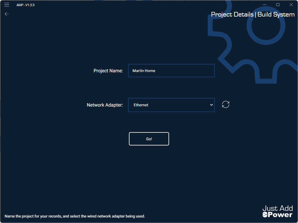
- Enter the project name and select your wired network adapter. Move to the next page.
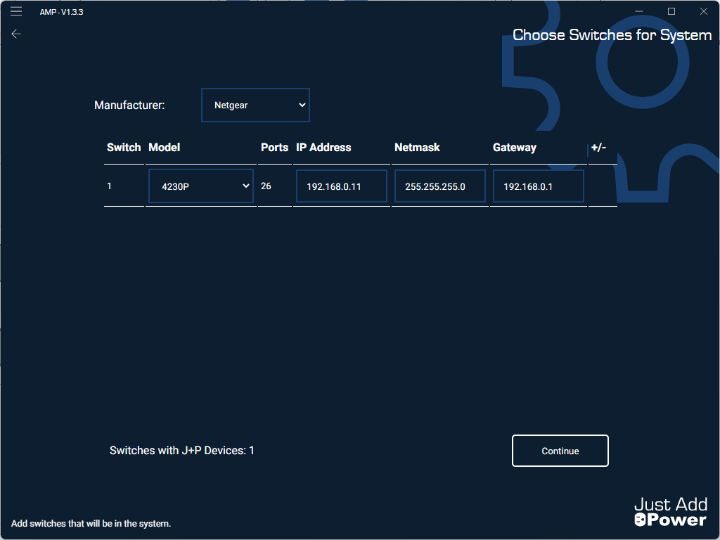
- Enter the new switch manufacturer and model, and assign IP address, subnet mask, and default gateway. Move to the next page.
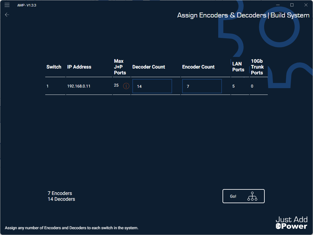
- Assign Decoder ports and Encoder ports for each switch according to the inventory performed earlier. Add one port for the Omega/Ultra System Controller, plus any expansion ports you decided to add. Move to the next page.
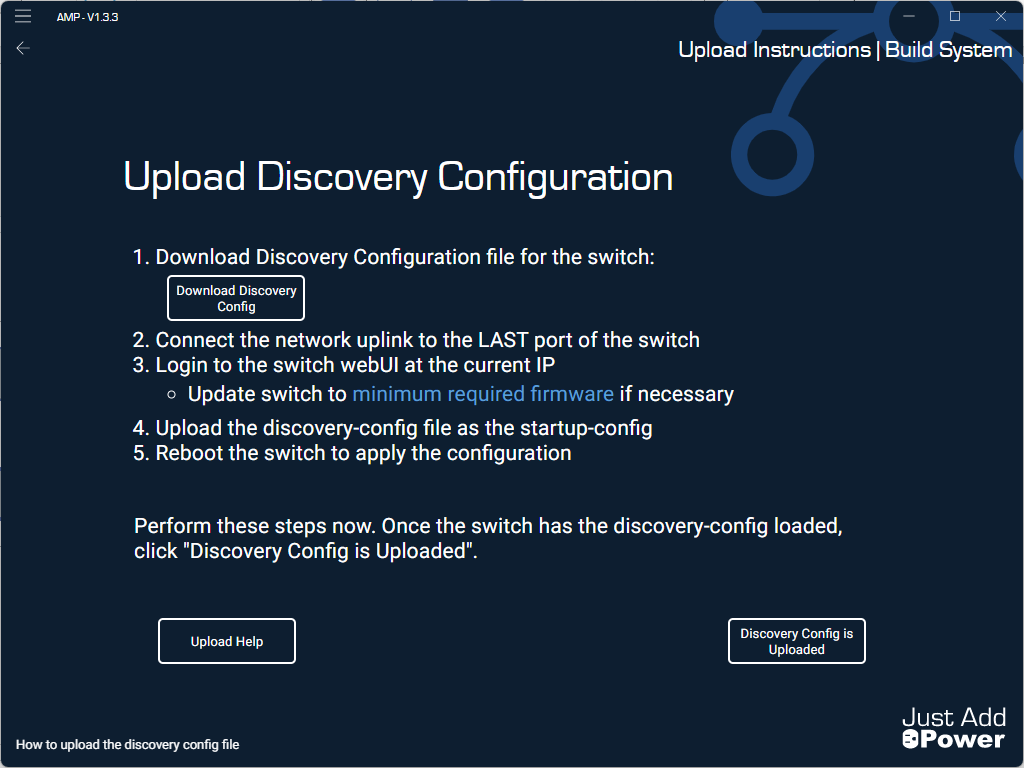
- Download the discovery configuration - the file that begins with dc - from AMP, and go to the webUI of each switch to upload the discovery configuration (instructions here). Move to the next page.
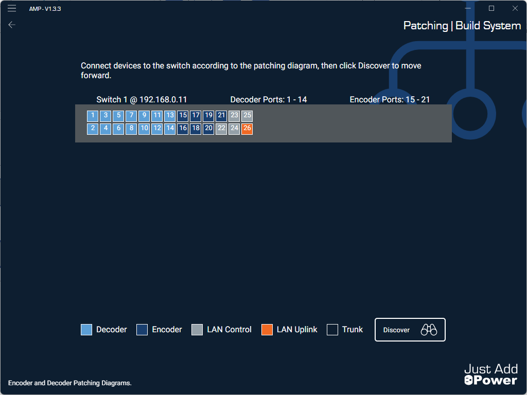
- Patch all Decoders and Encoders except the System Controller to the new switch using the diagram in AMP. The Convert JADConfig to AMP form will be integral to success on this step.
- Port 1 is open, because we are NOT connecting the System Controller yet. We will connect it later.
- Decoder 2 on the form connects to port 2 on the switch in the diagram. Decoder 3 connects to port 3, et cetera.
- Encoder 1 on the form connects to the first Encoder port on the switch in the diagram. This port is variable, as it depends on the number of Decoder ports. Continue with Encoder 2 and beyond in the same way.
- Enter the project name and select your wired network adapter. Move to the next page.
6. On the AMP top-left menu, select File --> Open Projects Folder
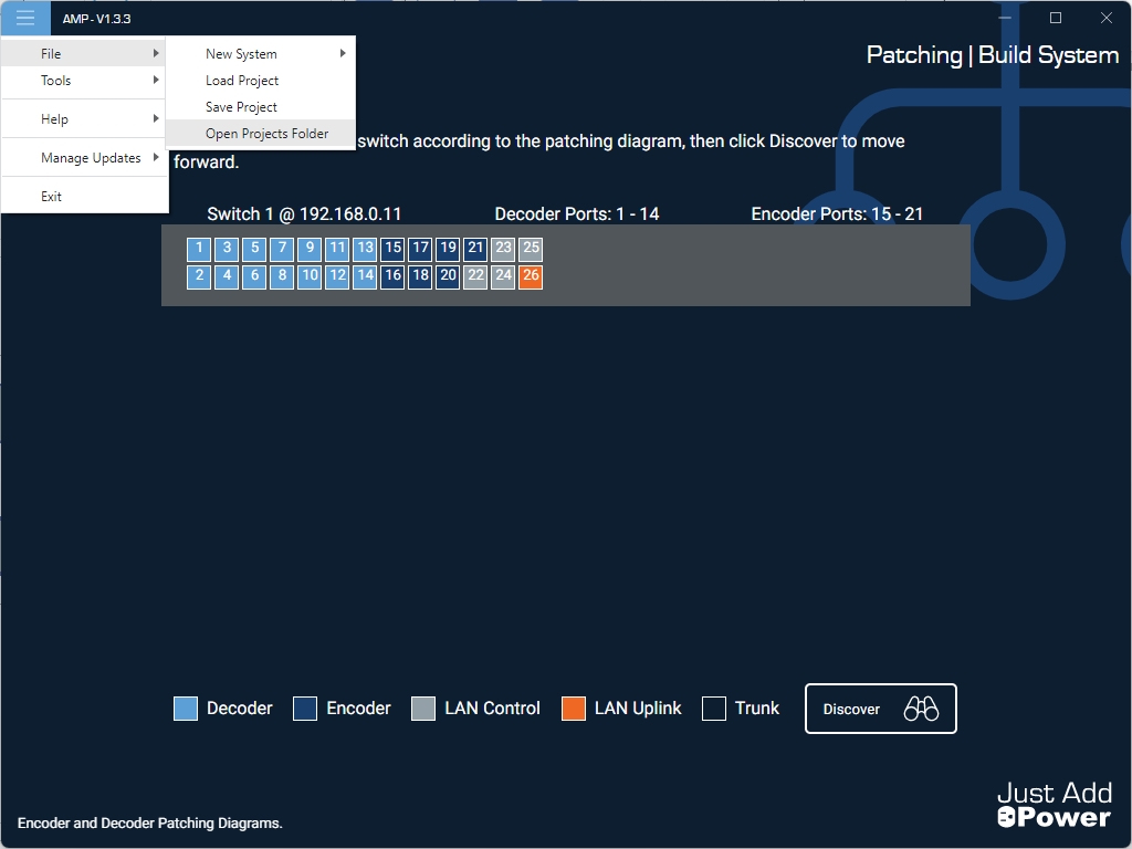
- File Explorer will open to the Project folder
- Navigate to the folder with the project name you entered
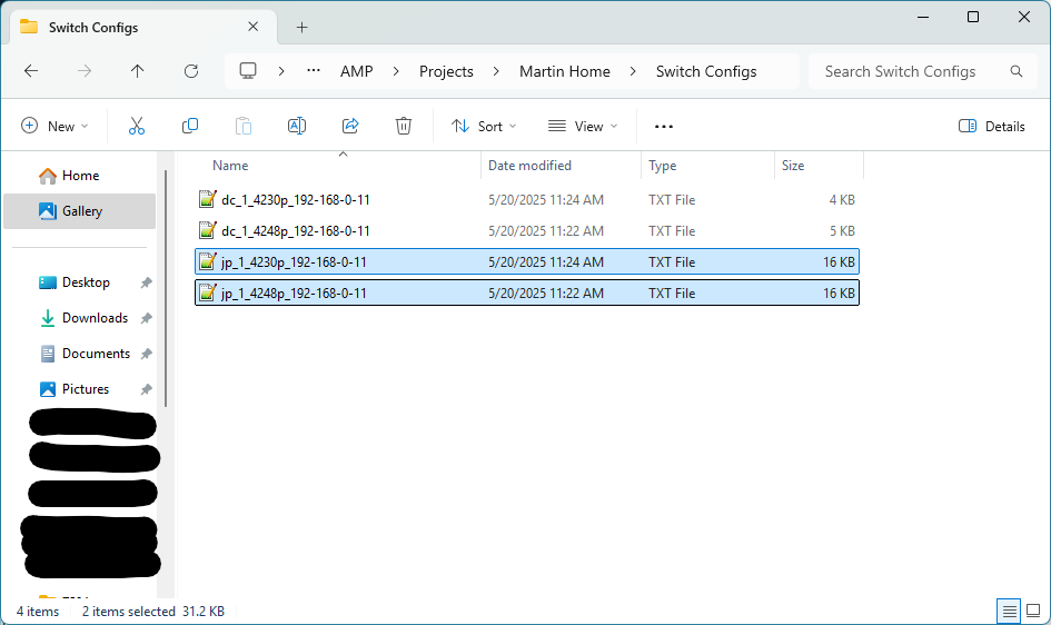
- Navigate to the Switch Configs folder
- Copy each final configuration file - beginning with the name jp - to your desktop. There will be one file per switch in the system. We will use these later. Example file name: jp_1_4248p_192-168-0-11.txt
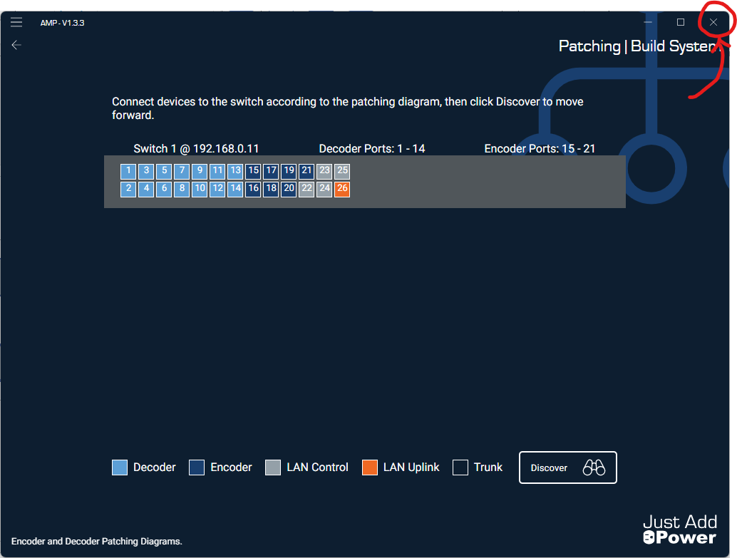
7. Close AMP while on the Patching page by clicking the X in the top-right corner. It is important that you DO NOT move forward to Discover.
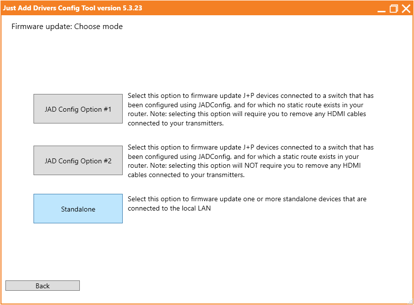
8. Run JADConfig. Select Firmware Update Only --> Standalone.
- Select the wired network adapter for your PC
- Allow JADConfig to discover devices and update firmware
- Close JADConfig
9. Connect the Omega/Ultra System Controller to Port 1 on the switch

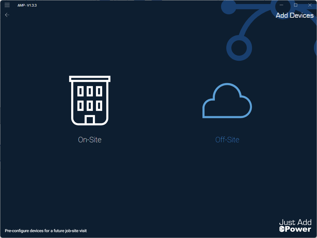
10. Run AMP again. Select Build & Expand --> Add Device --> Off-Site
- Select the wired network adapter for your PC and click Go!
- All 2G devices and the System Controller will be discovered. 2G devices are at their JADConfig IP addresses. The Omega/Ultra System Controller will probably be at 169.254.x.x.
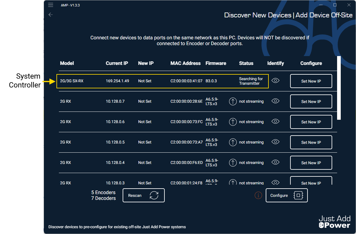
- DO NOT UPDATE FIRMWARE on any devices. The Omega/Ultra System Controller most likely needs a firmware update, but it will be done later.
11. Using the Convert JADConfig to AMP form, use Set New IP to apply the AMP-compatible IPs to every Just Add Power device
- In AMP, look for the IP address or MAC address of a device. Match that IP/MAC to a device on the form along with its new connection and IP
- Once the device is identified, select Set New IP and ensure the Just Add Power Subnet for all devices is set to 172.27.0.0/16.
- For a Decoder, select the Switch and Port the device is connected to
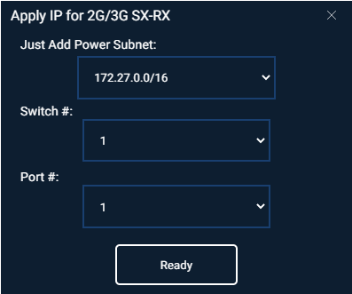
- For an Encoder, select the Encoder Number
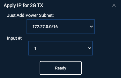
- For a Decoder, select the Switch and Port the device is connected to
- Once all devices have their new IP assigned, click Configure. On the popup, click Finish to return to the main menu.
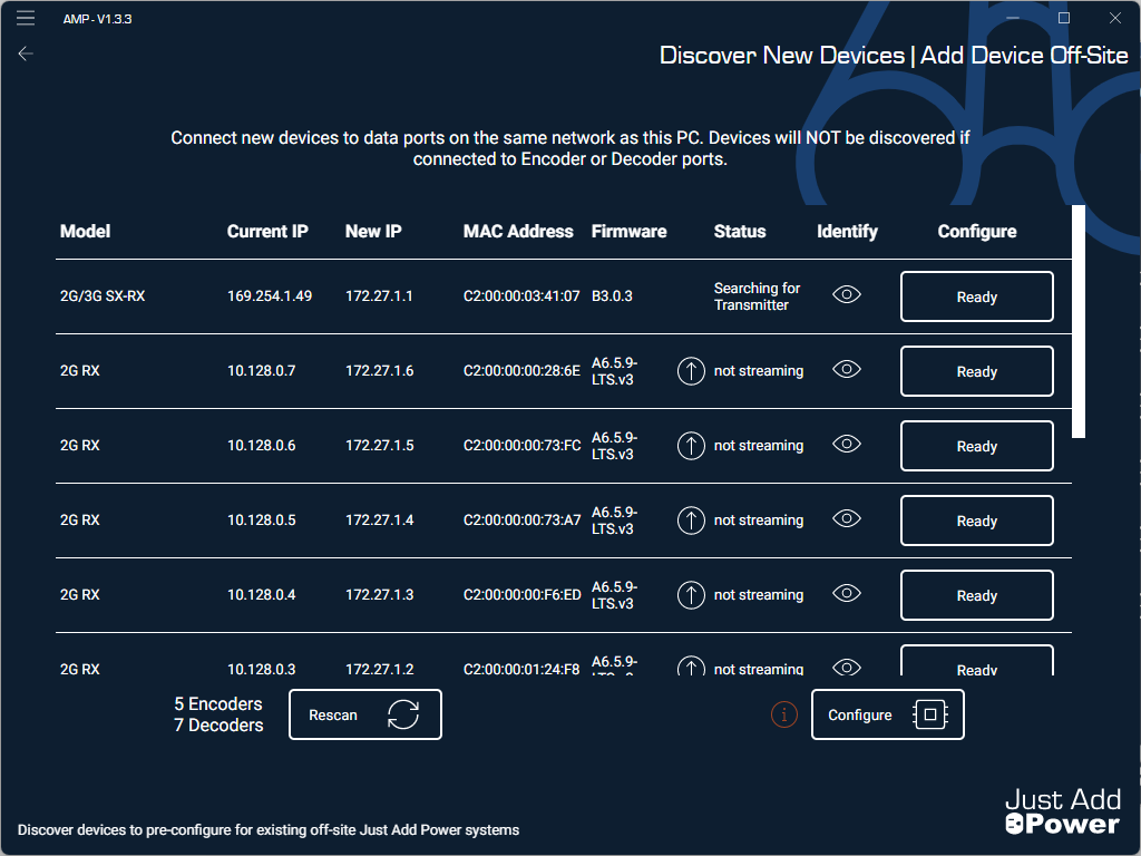
12. Close AMP when all devices have been configured.
13. Login to the webUI of each switch and upload the final configuration - the file that begins with jp from earlier - to the startup-config. Reboot the switch afterwards. (instructions here).
14. Login to the webUI of the router in the system and apply a Static Route to the router to be able to reach the Just Add Power devices at their new settings. The static route settings are:
- Destination IP: 172.27.0.0
- Netmask: 255.255.0.0
- Gateway: IP address of the switch (in this example, the switch IP is 192.168.0.11)
15. Login to the webUI of the System Controller to update it to the latest firmware version.
- Navigate to the firmware update section
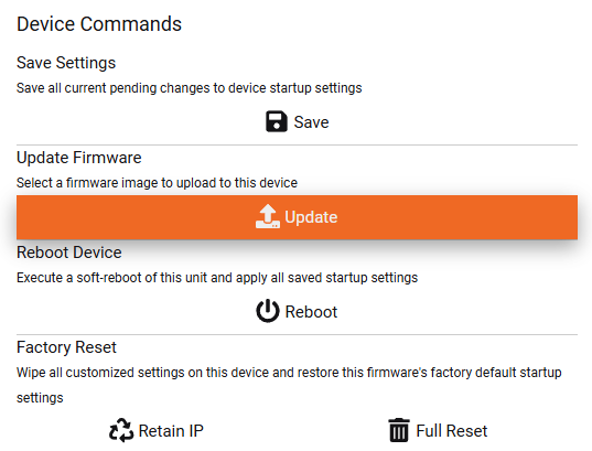
- Browse through your PC to C:\Program Files (x86)\Just Add Power\Advanced Matrix Programmer\resources\firmware and then to the folder that begins with B. That is firmware for the System Controller.
- Select the firmware file that matches the model of Omega/Ultra device you are using.
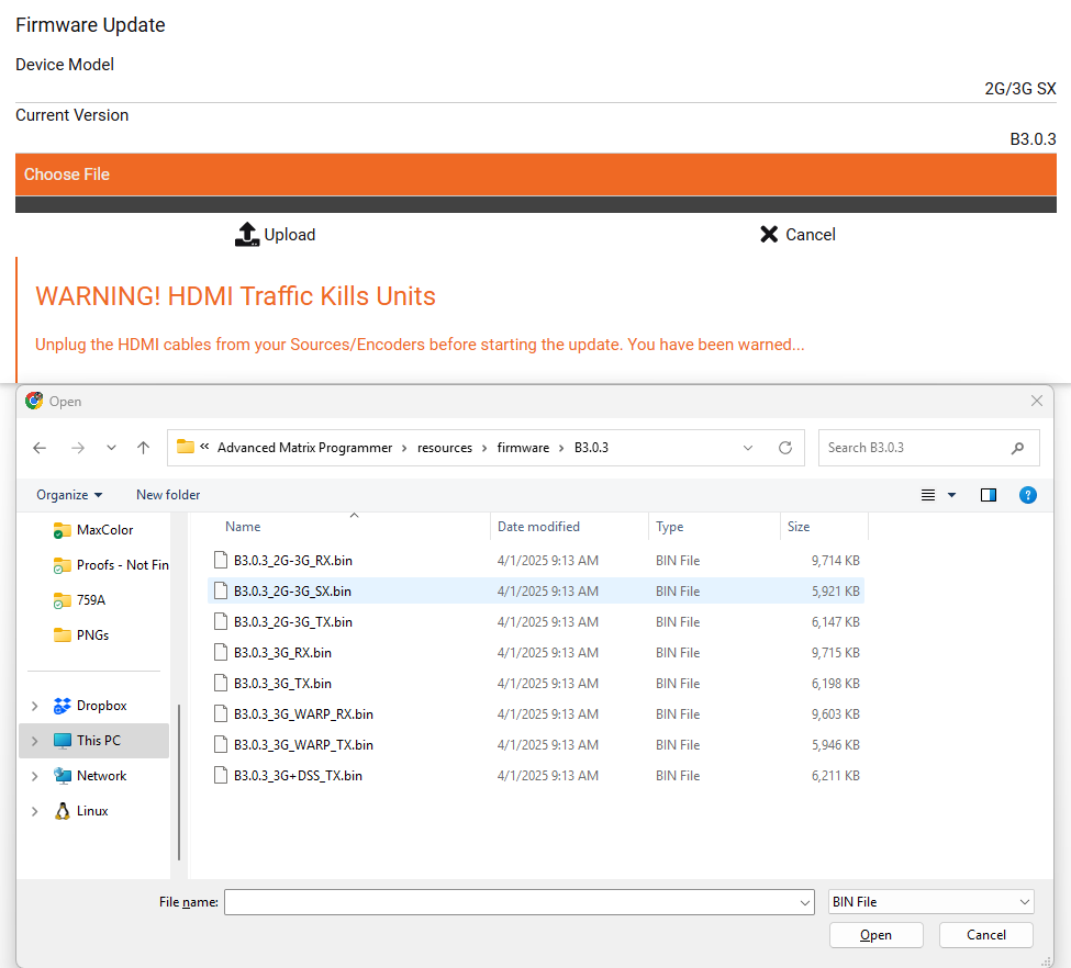
- Wait for the firmware update to finish.
16. This marks the end of the AMP conversion, and the Just Add Power system is ready to go.
17. Continue on to update the control system drivers as needed.
Convert an Established Omega/Ultra JADConfig Single-Switch System to AMP
Overview
JADConfig - released in 2011 and deprecated in 2022 - has assisted countless Installers with configuring Just Add Power systems. Starting with a group of unconfigured hardware, an Installer can build a fully-functional Just Add Power AV over IP matrix switching system in about 30 minutes.
JADConfig systems are still supported and we encourage systems built with JADConfig to remain that way. However, end-of-life or unavailability of switch replacements may make it necessary to convert to Advanced Matrix Programmer (AMP) for the system to remain functioning.
This article provides the instructions for Omega/Ultra installations configured using JADConfig to transition to AMP.
Requirements
- System contains exclusively Omega or Ultra Series devices on firmware Bx.x.x
- 2G Series devices are not supported by AMP. Omega or Ultra series devices running in 2G Series Mode are not supported by AMP.
- System is currently built using JADConfig standards. If JADConfig built the system, it meets all of these standards.
- The system only has one switch with Just Add Power devices connected to it.
- The switch in the system after the conversion - either the original switch or the replacement - is listed here as a compatible switch for AMP VLAN and has enough ports for all devices.
Fillable Form
This PDF assists with inventory of the current JADConfig system before converting to AMP. The more entered here, the easier the conversion will be.
jadconfig-conversion-form.pdf
This Excel spreadsheet assists with inventory like the above form, but has calculations that automatically determine where to move devices to in the AMP system.
jadconfig-conversion-calculator.xlsx
Convert Switch and Devices
We recommend following these steps carefully, as converting from JADConfig to AMP VLAN requires device labeling, cables disconnecting, wires moving, cables reconnecting, control system drivers updating, and IPs changing.
- Get an initial inventory of the system. The Takeover Job Assistance section will assist with finding these details:
- Switch manufacturer and model.
- Switch IP address, subnet mask, and default gateway (default gateway is typically the IP address of the router)
- Number of active Encoders.
- For each active Encoder, record the Encoder Number, the port on the switch it is currently connected to, and the name of the source it is connected to.
- Number of active Decoders.
- For each active Decoder, record the Decoder Number, the port on the switch it is currently connected to, and the name of the display it is connected to.
- Number of ports configured for Encoders (this may be different than active Encoders, as there may be empty ports on the switch that were created for future expansion).
- Number of ports configured for Decoders (this may be different than active Decoders, as there may be empty ports on the switch that were created for future expansion).
- Label the network cables connected to the switch according to Data connection, Encoder Number, or Decoder Number
- Before the conversion, port 1 is connected to the data network. Label this cable "Network Uplink"
- Encoder 1 is connected to port 2. Label this cable "Encoder 1".
- Continue for all Encoders.
- Decoder 1 will be connected to the switch, though the port will be different depending on the number of Encoders. Once you identify it, label the cable "Decoder 1"
- Continue for all Decoders.
- HDMI cables can remain connected throughout this process. Only the network cables will be moved.
- If the same switch is being used after the conversion, jump to Step 5
- If there is a replacement switch being installed, disconnect all cables from the old switch and install the new switch in its place. Do not connect any network cables to the new switch yet.
- Connect the "Network Uplink" cable to the last port of the switch. (Ignore SFP ports)
- Run AMP VLAN and follow the program to input the details recorded earlier:
- Switch manufacturer and model
- Switch IP address, subnet mask, and default gateway
- Upload the discovery configuration to the switch (instructions here)
- Input the Number of Decoders and Number of Encoders that corresponds to the number of PORTS configured for Encoders and Decoders. This count will include both active and empty ports.
- When the switch patching diagram appears, connect Encoder and Decoder ports to the switch
- Connect the "Decoder 1" network cable to port 1
- Continue for all Decoders in ports 2 and up
- Connect the "Encoder 1" network cable to the first Encoder port. This port will be different depending on the number of Decoders.
- Continue for all Encoders
- It is important that "Decoder 1" from the JADConfig system remains "Decoder 1" in the AMP VLAN system. The control system driver will read both of them as Decoder 1, even though they are connected to different ports. Connecting devices so they keep the same Decoder/Encoder numbering will save time during the control system update.
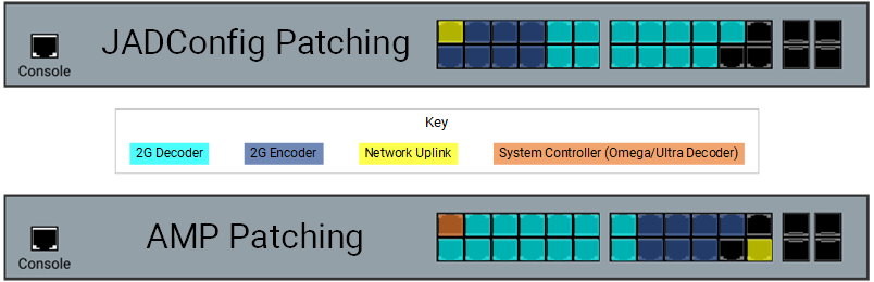
- For example, the images below show the same system with 10 Encoders and 10 Decoders. The top image is JADConfig port connections and the bottom image is AMP VLAN port connections.


Device Old Port New Port Network Uplink Port 1 Port 26 Encoder 1 Port 2 Port 11 Encoder 2 Port 3 Port 12 Encoder 3 Port 4 Port 13 Encoder 4 Port 5 Port 14 Decoder 1 Port 12 Port 1 Decoder 2 Port 13 Port 2 Decoder 3 Port 14 Port 3 Decoder 4 Port 15 Port 4
8. Continue with AMP VLAN until it is finished. All Just Add Power devices will be re-assigned new IP addresses during this process.
9. Save the Report File when asked to do so. This is the most important piece of documentation for the system, and will be helpful when updating the control system driver.
10. Video from Encoder 1 will show on all Decoders in the system.
Convert an Established Omega/Ultra JADConfig Stack-Switch System to AMP
Overview
Advanced Matrix Programmer provides a path forward for all legacy installations configured using JADConfig in a stacked topology using two or more switches.
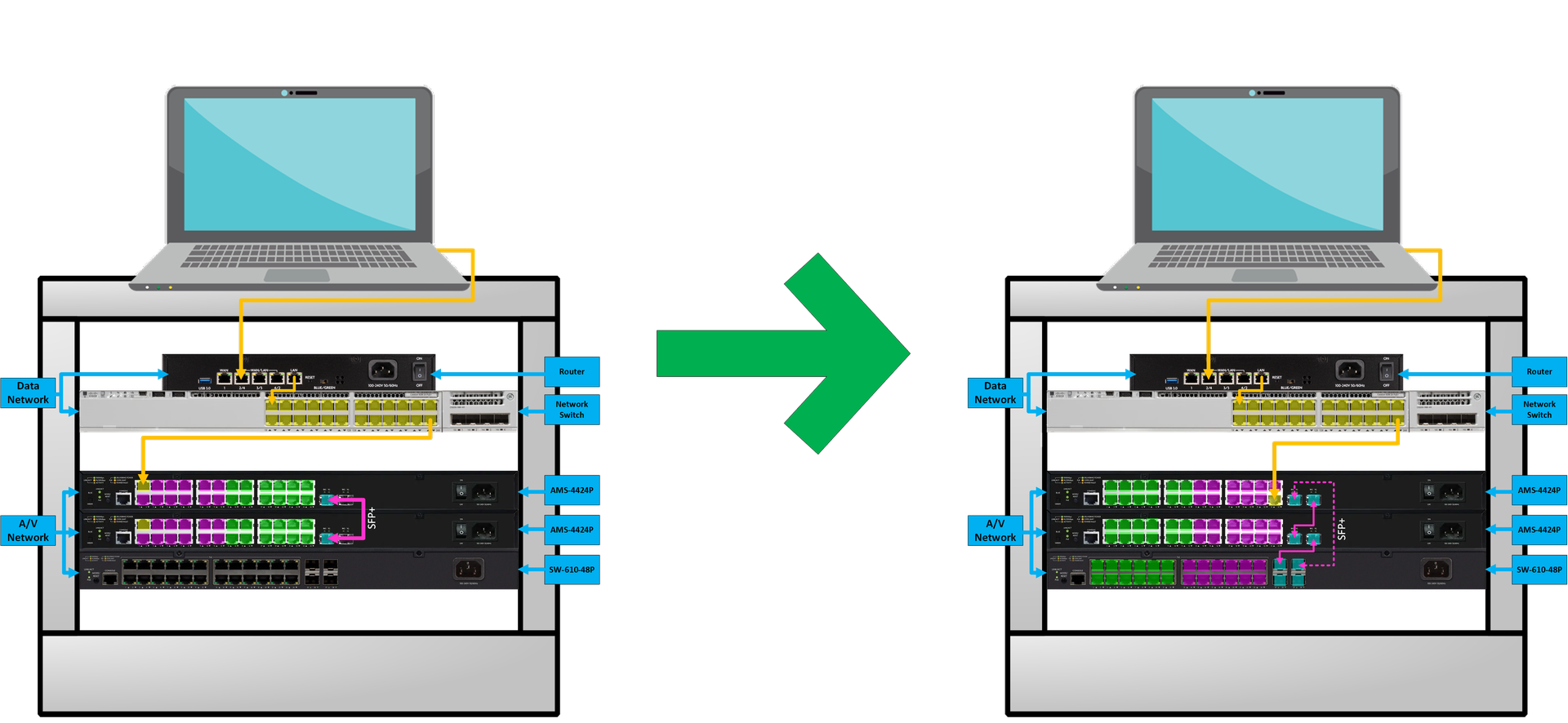
This article covers the steps required to migrate from Stacking to Trunking, combining or replacing any existing legacy multi-switch models at the job-site with any current multi-switch model of the same manufacturer.
For all examples, we will be running a 3-switch system with two Luxul 4424P's and a single SW-610-24P.
Supported Switch Models
| Model | Ports On | POE Devices per Switch | SFP+ Ports |
| AMS-4424P | Rear | 24 | 2 |
| XMS-7048P | Front | 48 | 2 |
| SW-610-24P-R | Rear | 24 | 4 |
| SW-610-48P-F | Front | 48 | 4 |
| SW-615-24P-F | Front | 24 | 4 |
| SW-615-48P-F | Front | 48 | 4 |
Fillable Form
This PDF assists with inventory of the current JADConfig system before converting to AMP. The more entered here, the easier the conversion will be.
jadconfig-conversion-form.pdf
This Excel spreadsheet assists with inventory like the above form, but has calculations that automatically determine where to move devices to in the AMP system.
jadconfig-conversion-calculator.xlsx
Instructions & Preperations
*Requires Local or Data Network Up-link accessibility at each switch location*
*When disabling Stacking, all switches will use the SAME IP Address*
Run JADConfig "Read Switch Config" for a report file before getting started.
See JADConfig Report File for SWITCH ID to MAC Address association.
Part 1: Generate Discovery Configuration Files
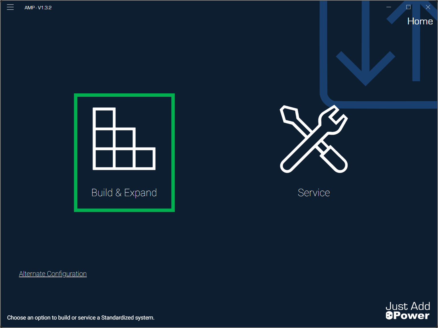
- Open Advanced Matrix Programmer (AMP).
- Select Build & Expand.
- Select Build New.
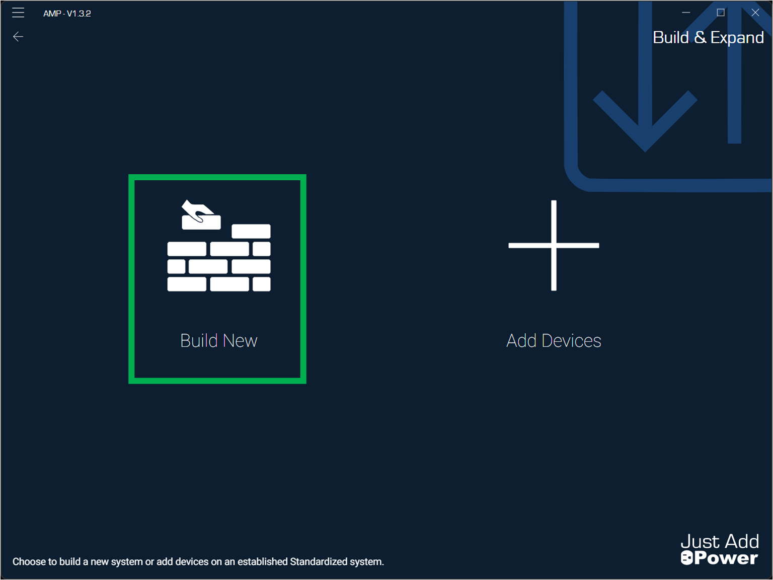
- Name "Project" after the job-site & Click Go!
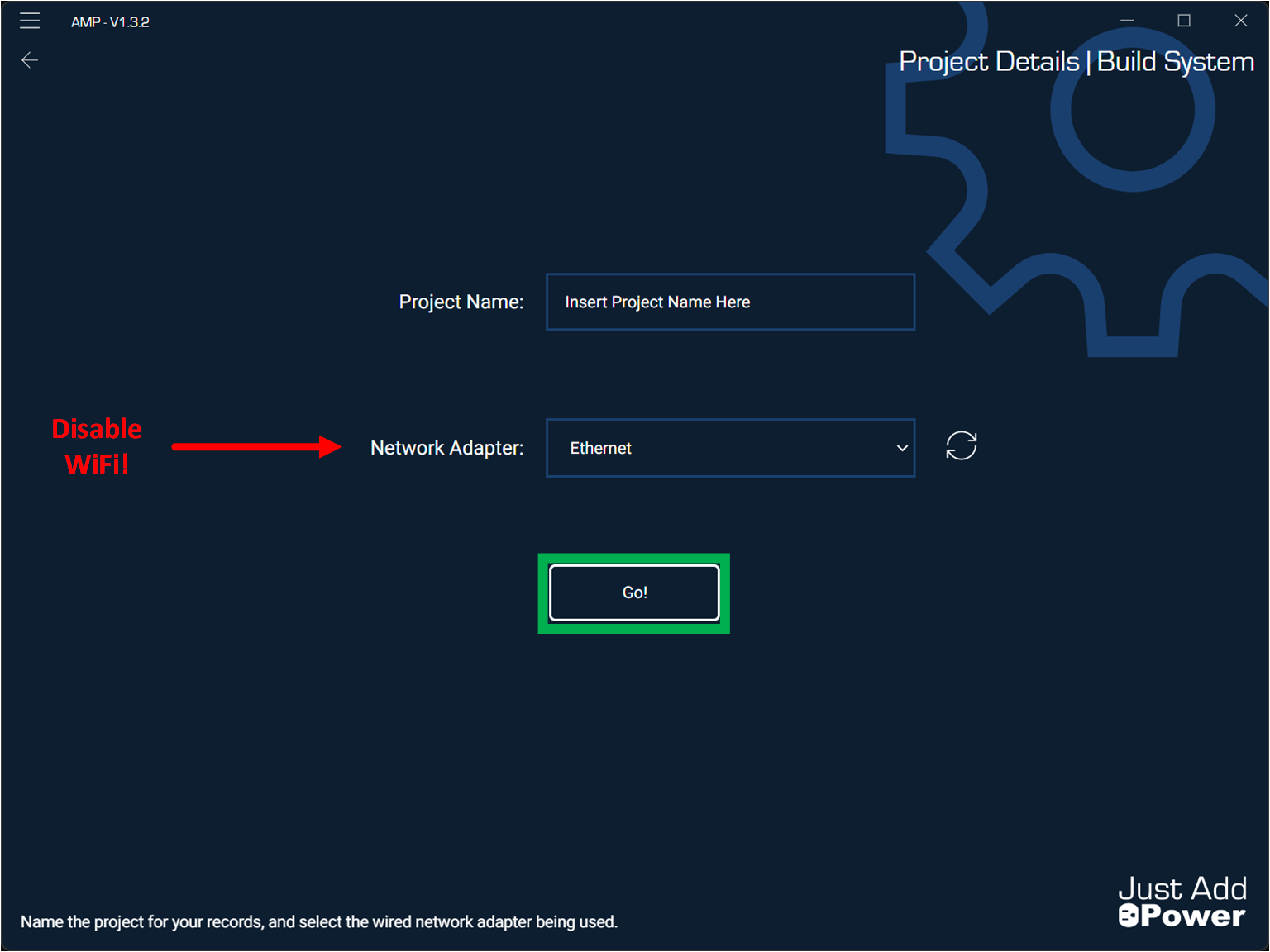
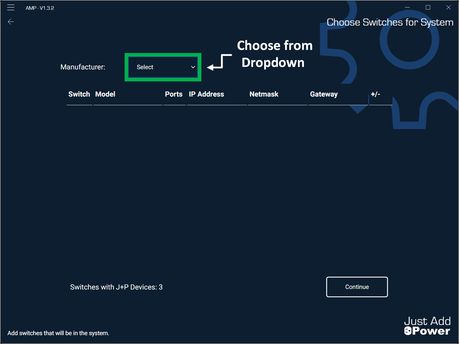
- Select Switch Manufacturer.
- Select Model for Switch ID 1.

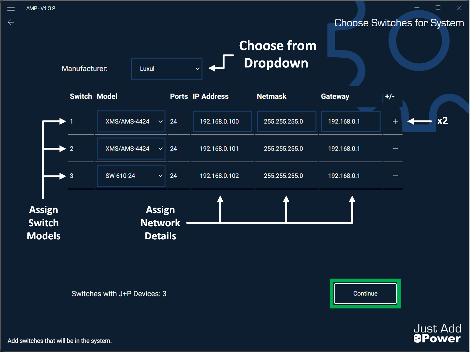
- Use the "+' symbol to add multiple switches'
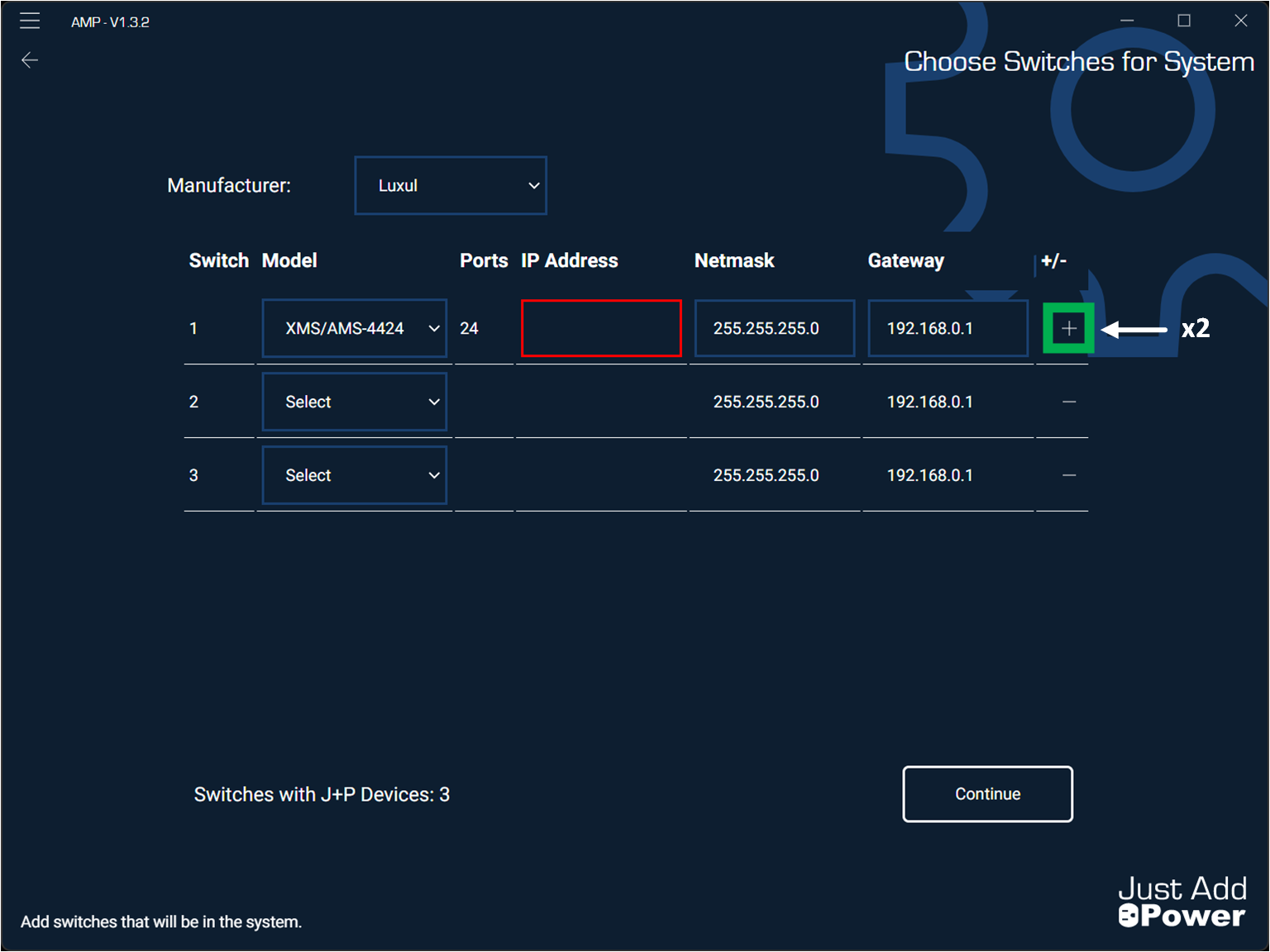
- Assign Models for Switch ID 2 & 3.
- See JADConfig Report file to confirm switch order.

- See JADConfig Report file to confirm switch order.
- Assign Switches with IP Addresses.
- All secondary switches are assigned IP addresses in sequential order starting from the primary switch.
- Example:
Switch #1: 192.168.0.100, 255.255.255.0, 192.168.0.1
Switch #2: 192.168.0.101, 255.255.255.0, 192.168.0.1
Switch #3: 192.168.0.102, 255.255.255.0, 192.168.0.1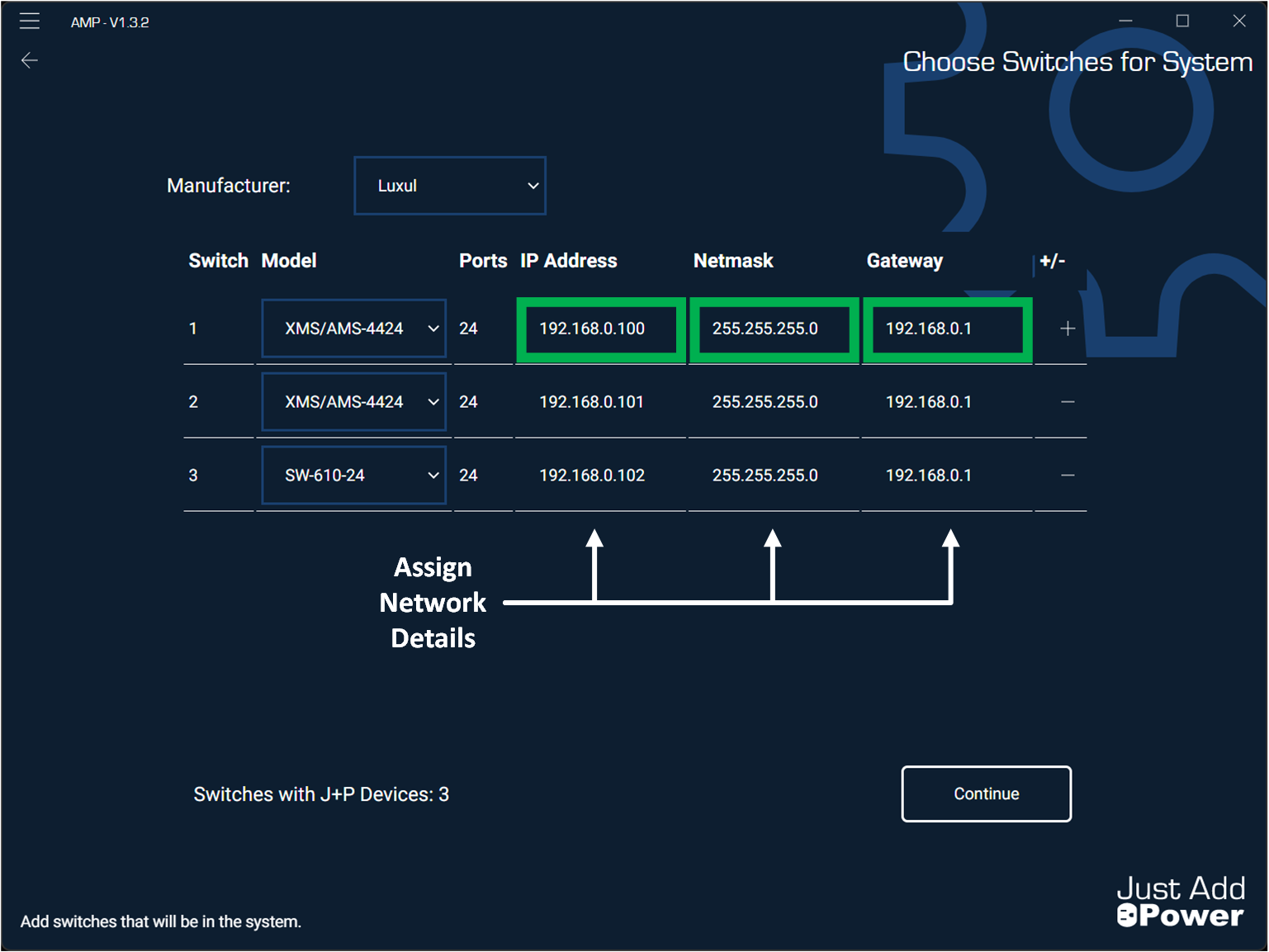
- Click Continue
- Assign Encoder & Decoder Counts for each switch.
- Check your JADConfig report file to confirm the Encoder & Decoder counts for each switch.

- Check your JADConfig report file to confirm the Encoder & Decoder counts for each switch.
- Click Go!
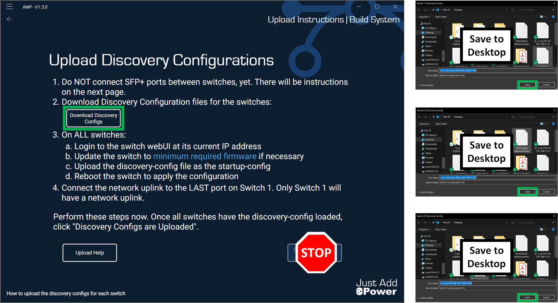
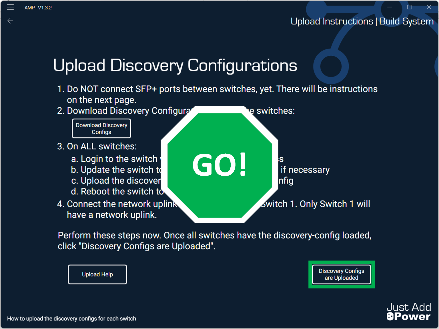
- Click "Download Discovery Configs"
- Save .txt files to Desktop for ease of access.
- Don't click "Discovery Configs are Uploaded".
Part 2: Setup Existing AMS-4424/XMS-7048 Switches
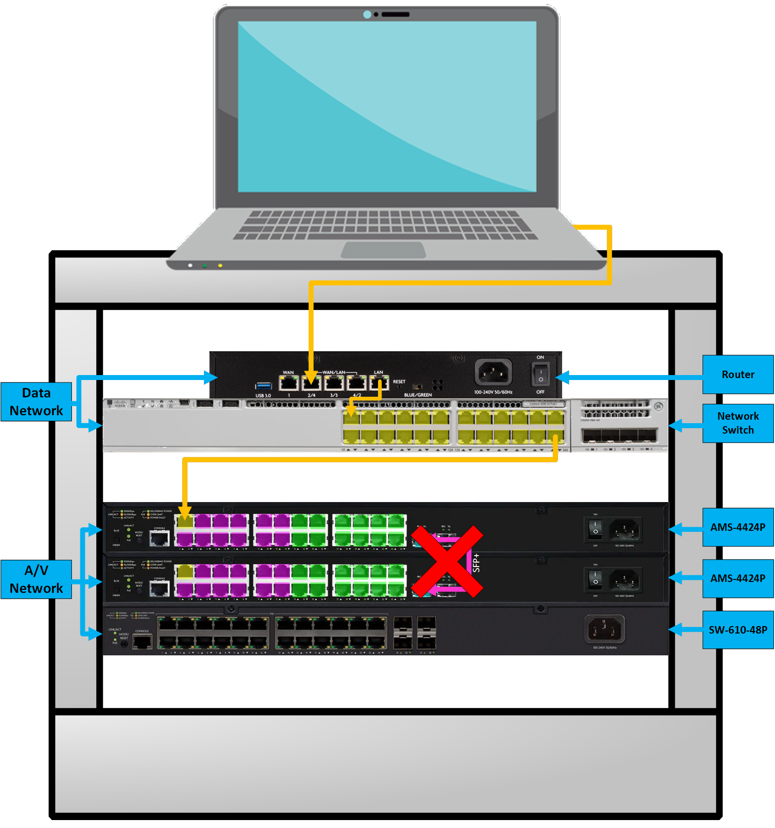
- Remove SFP+ cables from all switches in the stack.
- Login to Stack Switch via web browser using the Switch Stack IP Address.
- Navigate to: Configuration > Stack
- Uncheck "Stacking Enabled".
- Set Switch ID to "1".
- Set Priority to "1".
- Check to Delete any extra switches listed.
- Click Save.

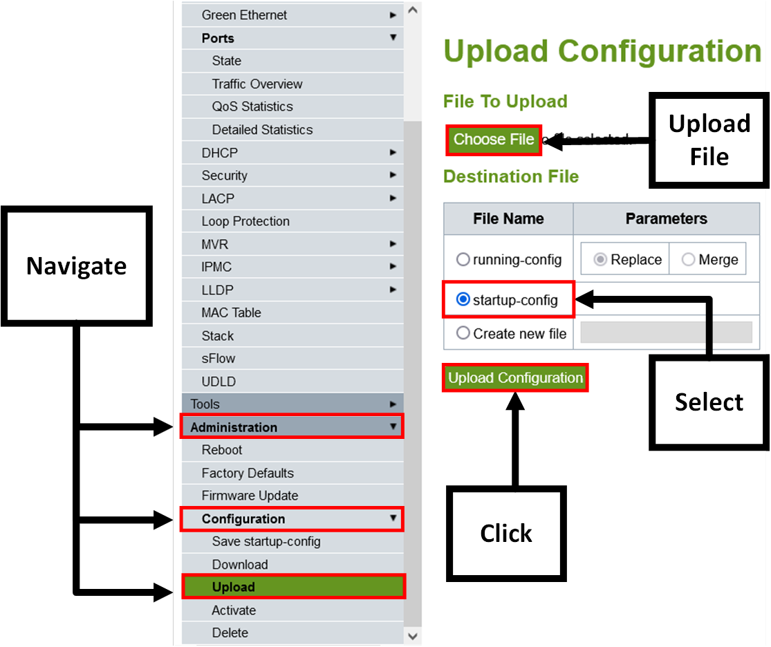
- Navigate to: Administration > Configuration > Upload
- Choose file: "dc_1_[Switch Model]_[SwitchIP].txt".
- Select bubble for "startup-config".
- If "startup-config" is not listed, use "Create New File" and name it "startup-config".
- Select Upload Configuration
- Reboot Switch
- Disconnect Local/Data Network from Stack 1 & Reconnect to Stack 2, Port 1.
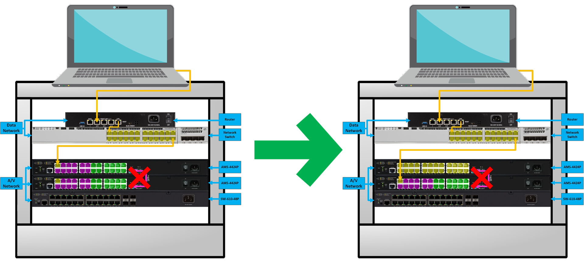
- Login to Stack Switch via web browser using Switch Stack IP Address.
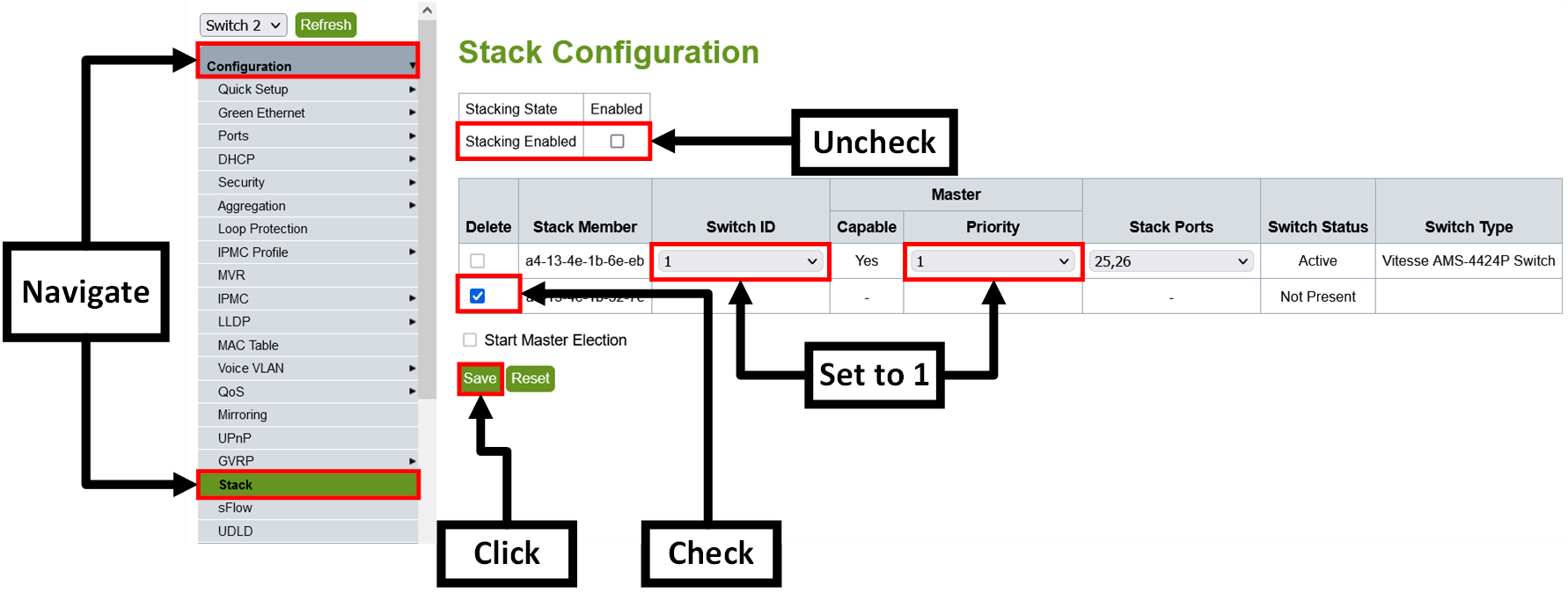
- Navigate to: Configuration > Stack
- Uncheck "Stacking Enabled".
- Set Switch ID to "1".
- Set Priority to "1".
- Check to Delete any extra switches listed.
- Click Save.
- Navigate to: Administration > Configuration > Upload
- Choose file: "dc_2_[Switch Model]_[SwitchIP].txt"
- Select bubble for "startup-config".
- If "startup-config" is not listed, use "Create New File" and name it "startup-config".
- Select Upload Configuration.
- Navigate to: Administration > Reboot
- Reboot the Switch.
- Repeat steps above for additional switches.
Part 3: Adding a SW-610-24P/48P
- Connect Local or Data Network Up-link to the last port of the switch.
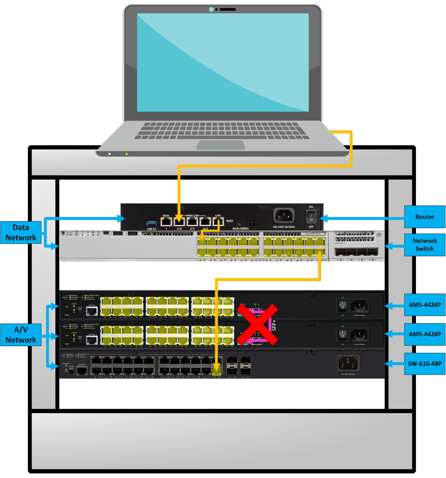
- Open the Webui of the switch.
- Choose File: "dc_[#]_[SW-610-24P/48P]_[SwitchIP].txt"
- Select bubble for "startup-config.
- If "startup-config" is not listed, use "Create New File" and name it "startup-config".
- Select Upload Configuration
- Reboot the Switch.
Part 4: Continue with AMP
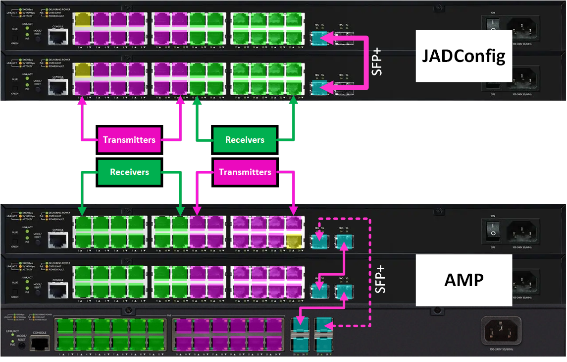
- Reconnect SFP+'s
- Connect one SFP+ Cable between each switch.
- Switch 1 Connects to Switch 2.
- Switch 2 Connects to Switch 3.
- Repeat until last switch is connected.
- Optional: Connect the first switch to the last switch for redundancy.
- Move Local or Data Up-link to the last port of switch 1. (See diagram below)
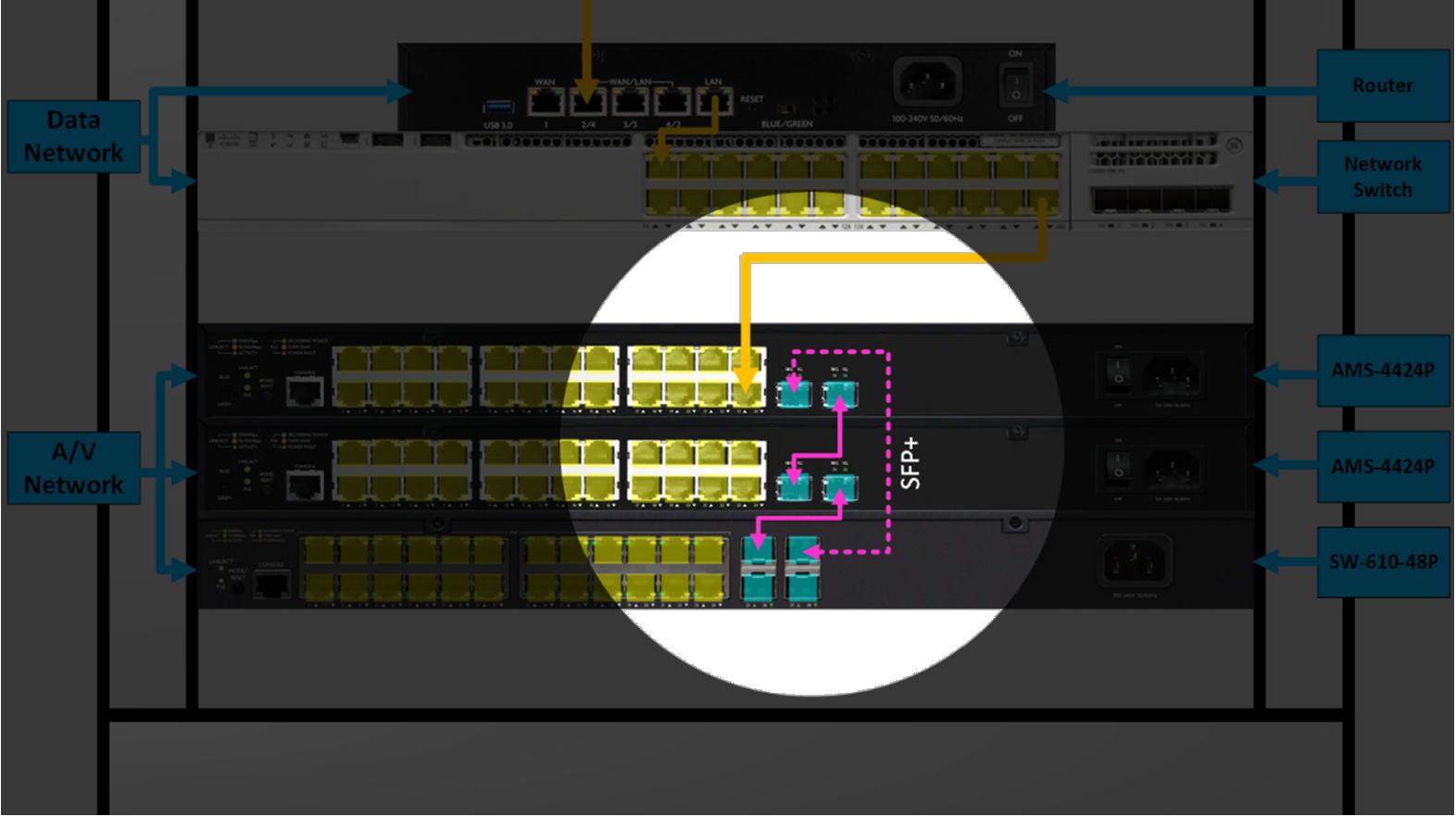
- Return to AMP
- Click "Discovery Configs are Uploaded"
- Physical Layout of Transmitters and Receivers are reversed in AMP.
- Continue normally with Advanced Matrix Programmer (AMP) in order to finalize the system configuration.
- **DISCLAIMER!! It is recommended to label all network runs before re-patching, otherwise re-configuring the control system might be difficult if runs are patch out of sequential order.**
- **DISCLAIMER!! It is recommended to label all network runs before re-patching, otherwise re-configuring the control system might be difficult if runs are patch out of sequential order.**