
JAP - Control System IntegrationControl4Download - Control4 Driver for AMP Alternate SystemsOverviewDownloadDriver DescriptionRecent ChangesDownload - Control4 Driver for JADConfig SystemsOverviewCompatibilityDownloadsVersionsSwitching Multiple DisplaysControl4 OS3ChangesKnown IssuesSetup a Tiler with Control4's MultiDisplay ManagerOverviewTraining VideoPart 1: Room, Drivers, and ConnectionsPart 2: Agents and MultiDisplay ManagerPart 3: Programming MacrosPart 4: Refresh Navigators and Go!Download - Control4 Driver for AMP Standardized SystemsOverviewDownloadBasic Driver SetupSwitching Driver - avswitch_ip_justaddpower_jpsw.c4zEndpoint and Feature Control Driver - proxy_ip_JustAddPower_TerminalServer.c4zVideo GuideVersionsSwitching Multiple DisplaysChangesOther DriversSetup Endpoint Control (RS232, IR, CEC) for Encoders & DecodersOverviewRequirementsSetup RS232Setup IRSetup CECCEC Programming with Samsung DisplaysSetup a Video Wall with Control4's MultiDisplay ManagerOverviewTraining Video2x2 Video Wall TemplatePart 1: Add Room and DriversPart 2: Agents and MultiDisplay ManagerPart 3: Programming MacrosPart 4: Refresh Navigators and Go!Other systems
Control4
Download - Control4 Driver for AMP Alternate Systems
Overview
Contracted by Just Add Power.
Controls Omega, Ultra, and MaxColor Just Add Power devices setup by AMP Alternate.
Requires Just Add Power justOS firmware B2.1.0 or greater (applied by AMP).
Switching driver supports up to 64 inputs and 64 outputs.
Also includes endpoint control driver and documentation.
Download
Download Control4 Alternate Driver
jp-driver-manual-control4-multicast.pdf
Driver Description
Matrix Control v2.07
- avswitch_ip_JustAddPower_multicast_32x32.c4z
- Matrix control - switch any display to watch any source
- Maximum of 32 inputs and 32 outputs. Works for any project with less than that.
- Load only 1 into the system (this or the 64x64, not both)
- avswitch_ip_JustAddPower_multicast_64x64.c4z
- Matrix control - switch any display to watch any source
- Maximum 64 inputs and 64 outputs. Works for any project with less than that.
- Load only 1 into the system (this or the 32x32, not both)
Endpoint & Feature Control v3.02
- proxy_ip_JustAddPower_TerminalServer.c4z
- Endpoint control - control a display or source with RS232, IR, or CEC
- Feature control - control Just Add Power features like video wall or Tiling Transmitter layouts
- Load 1 per Receiver and 1 per Transmitter that needs Endpoint or Device control
Recent Changes
- Endpoint and Feature Control driver
- Add an IR Output
- Add support for MaxColor IR
- Matrix Control driver
- adds more detailed Operational Mode information
- Adds compatibility with OS 2.10.6
- Removes DISCONNECT_OUTPUT response (was setting to channel 0 when a room was turned off)
Download - Control4 Driver for JADConfig Systems
Overview
This driver package provides Matrix Control, Endpoint Control, and Feature Control of a Just Add Power VLAN switching system configured with JADConfig.
- Matrix Control - switch any display to watch any source
- Endpoint Control - manage sources and displays with IR, RS232, or CEC
- Feature Control - manage features of Just Add Power like video wall, image pull, tiling control
Driver supports up to 256 inputs and 256 outputs.
Contracted by Just Add Power.
Compatibility
- This driver is NOT COMPATIBLE with:
- systems configured with AMP - both Standardized and Alternate configurations
- Luxul SW-510-48P-F switches
Downloads
Control4 JADConfig Drivers
Control4 JADConfig Manual
Versions
- Matrix Control drivers - only load 1 driver for the switch manufacturer in the system. Larger sizes can cause Composer to crash if the virtual matrix does not have enough available memory. These driver sizes represent maximum sizing and will support any smaller system.
- avswitch_ip_JustAddPower_Luxul.c4z - Luxul Matrix Control driver v1.20
- Unlabeled driver is 256x256.
- Various sizes are available - 32x32, 64x64, 64x128, 128x128
- avswitch_ip_JustAddPower_CiscoSG300.c4z - Cisco Matrix Control driver v2.21
- Unlabeled driver is 256x256.
- Various sizes are available - 32x32, 64x64, 64x128, 128x128
- avswitch_ip_JustAddPower_Luxul.c4z - Luxul Matrix Control driver v1.20
- proxy_ip_JustAddPower_TerminalServer.c4z - Just Add Power Endpoint and Feature Control driver v3.01
- Behaves like a display in Composer with an HDMI input, serial output, IR output, and CEC power on and off commands
Switching Multiple Displays
The Matrix Control driver gives the ability to switch multiple outputs simultaneously using a device specific command from the Programming tab in Composer.
Command Example Syntax:
Switch Outputs 1 thru 16 to watch Input 1
SW1,2,3,4,5,6,7,8,9,10,11,12,13,14,15,16=1
Switch Outputs 1, 2, 5 and 6 to watch Input 3
SW1,2,5,6=3
Note: The command is case sensitive and must match the exact syntax in order to function.
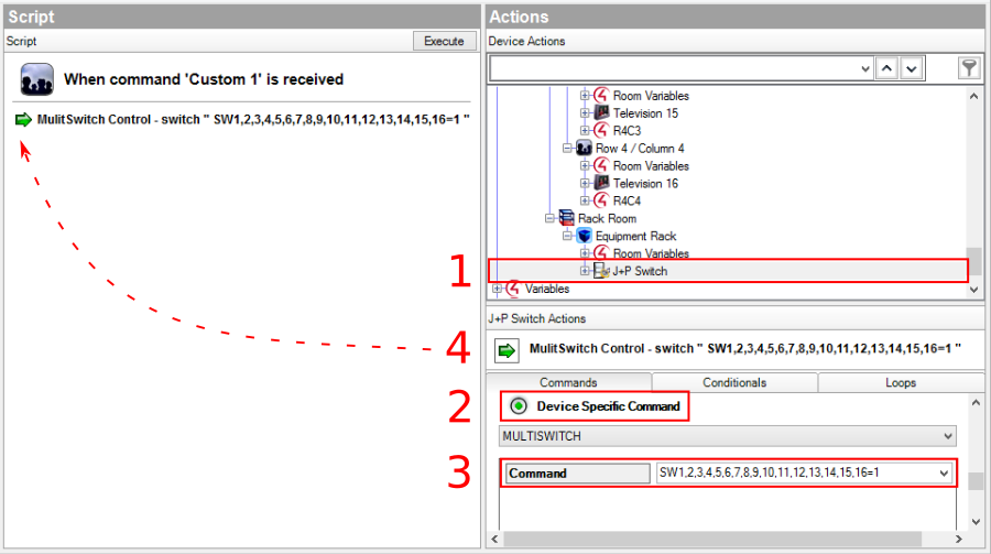
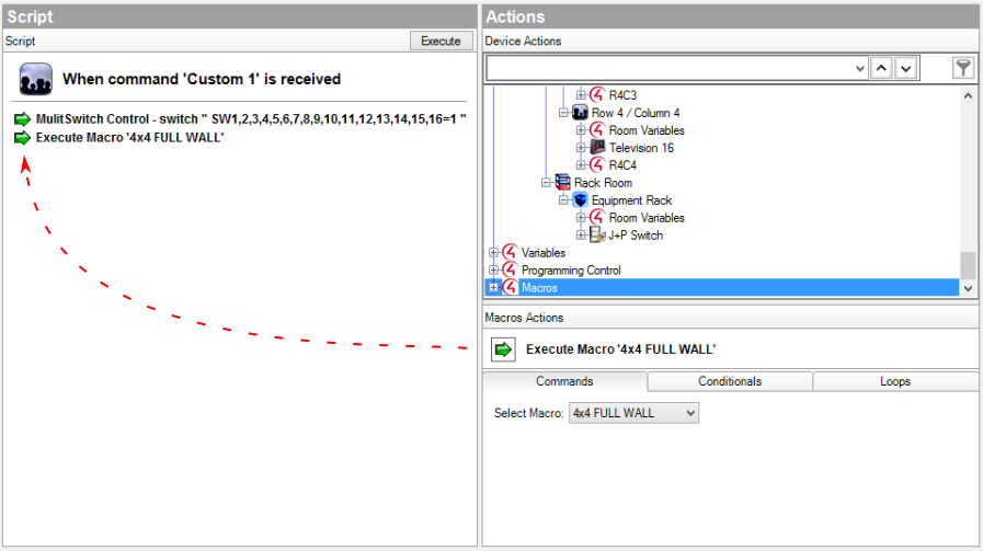
The MULTISWITCH command is great when paired with video wall layouts.
Control4 OS3
The update to OS3 required the driver file type to change from .c4i to .c4z. Updating from the .c4i version to the .c4z version cannot be done through the Update Driver option in Composer. Instead, the new version must be loaded separately and reprogrammed with the settings from the old driver.
If the update to OS3 causes the Operational Mode to report as "Connecting..." follow these steps to remedy it:
- Ensure you are running driver v1.11 or later. v1.10 had corner cases where the driver would not properly reconnect after the switch or processor rebooted.
- Go to Connections --> Network. Disconnect the IP and re-enter the IP from the switching driver.
- Go to System Design and select the switching driver. Remove the license key, click Set, re-enter the license key, and click Set again.
- Reboot the Director if Steps 1-3 did not restore the Operational Mode to Licensed. This will restore the driver to a functional state.
Changes
- Terminal Server driver now has IR output ports and supports IR control directly. No more Global Cache driver!
- Fixes issues with larger systems taking a long time to load
Known Issues
- Updating the username/password entry in the Matrix Control driver does not always update properly. Power cycle the Control4 processor to fix permanently.
- Legacy .c4i versions of the driver cause the driver to get stuck at Connecting... when running on OS3. Update to the latest version of the driver using the OS3 instructions above to resolve this.
Setup a Tiler with Control4's MultiDisplay Manager
Overview
The instructions in this article will use Control4's MultiDisplay Manager to program an interface for either the UL-759A or MC-QX.
Before beginning this article, it is expected that you have already:
- Configured all Just Add Power devices
- Configured the switching driver by connecting other sources and displays
- Added all non-Just Add Power drivers to the Composer project
In Control4 Composer OS3, a single Just Add Power Tiling Encoder is represented by 6 drivers:
- Four Just Add Power RS232-IP Server drivers represent the four Decoders in the Tiler and provide source switching.
- One Just Add Power RS232-IP Server driver represents layout control of the Tiling Encoder
- One generic HDMI source driver represents source switching for the Tilers video signal so it is a selectable source. We typically use the PC-UI button driver.
Latest Control4 drivers available here.
Note: As of Composer 3.4.0, MultiDisplay Manager is not available on many iPhones.
Training Video
If you'd rather watch a video:
Part 1: Room, Drivers, and Connections
The Tiler is available to all rooms, so control is best accessed by giving it a room of its own.
- Create a new Room (we name ours Tiling)
- Add 4 Just Add Power RS232-IP Server drivers to the Tiling Room. These represent the four Decoders in the Tiler for source selection. (We name ours Tiler DE1, DE2, DE3, DE4)
- In Properties for each driver, set the IP address for each Decoder according to the Report File.
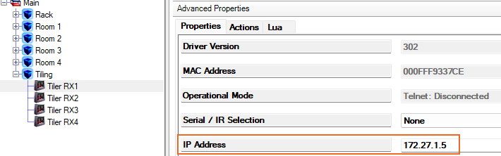
- In Control/AV Connections, connect each driver to the Just Add Power Switching Driver Output according to the Report File.
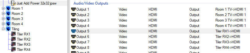
- In Control/AV Connections, select the Tiling Room. Tiler DE1 is already the Video End-Point for the room (or whichever driver was added first). Connect DE2, DE3, and DE4 as Additional Video End-Points. This makes these displays available to the MultiDisplay Manager.
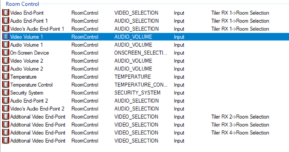
- These drivers are done!
- In Properties for each driver, set the IP address for each Decoder according to the Report File.
- Add 1 Just Add Power RS232-IP Server driver to the Room that holds all of the server equipment. This represents layout control of the Tiling Encoder. (We name ours Tiler EN)
- In Properties, set the IP address for the Encoder according to the Report File.

- This driver is done! No Control/AV Connections are needed.
- In Properties, set the IP address for the Encoder according to the Report File.
- Add 1 generic HDMI source driver to the Room that holds all of the server equipment. This represents source selection for the Tiler. (We use the PC - UI Button driver and name it Tiler Source)
- In Control/AV Connections, connect the Tiler Source driver to the Just Add Power Switching Driver Input according to the Report File.

- This driver is done! It is only here to represent the Tiler for source selection.
- In Control/AV Connections, connect the Tiler Source driver to the Just Add Power Switching Driver Input according to the Report File.
- Room, Drivers, and Connections are done!
Part 2: Agents and MultiDisplay Manager
Now that all Connections are made, the MultiDisplay Manager allows the user interface to control more than one display in the same room.
- Under Agents in Composer, click on Add, and add MultiDisplay Manager to the Agents window if not already there.
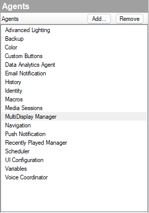
- In MultiDisplay Manager on the Dashboard tab, the Tiler behaves as a Wall. Click Add Wall and set the Audio Zone (Room) to Tiling.
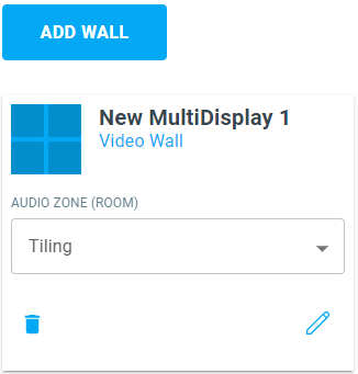
- Click the Pencil icon to configure the Tiler.
- Set the Wall Name - this is how the user will see it on the interface. (We named ours Tiling.)
- Set Audio Zone (Room) to the Tiling Room.
- Set the Audio Source if you have a specific source that you want to use (we leave our Audio Source blank, so audio doesn't change when the Tiler is selected).

- Set Layout to 2 Rows and 2 Columns and click Get Started. The layout is how the user will see it on the interface. The default layout is a 2x2 grid. Rearrange as you like (We leave ours at default).
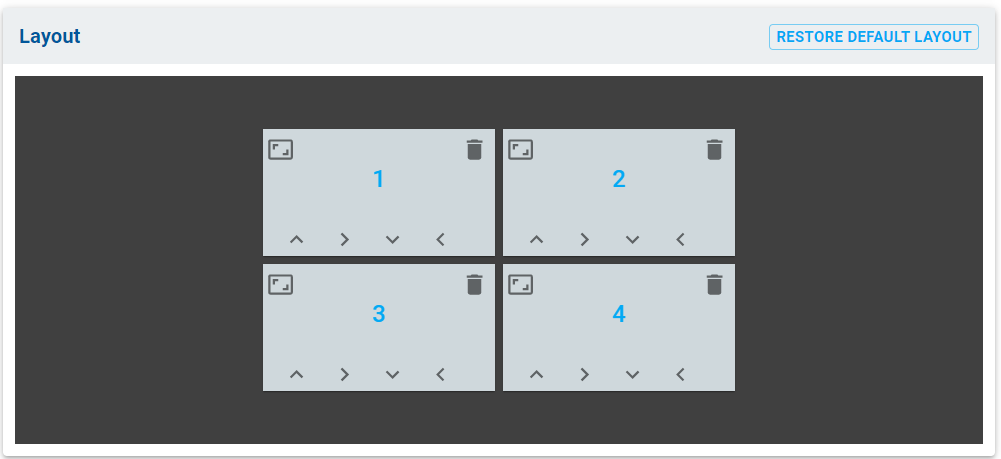
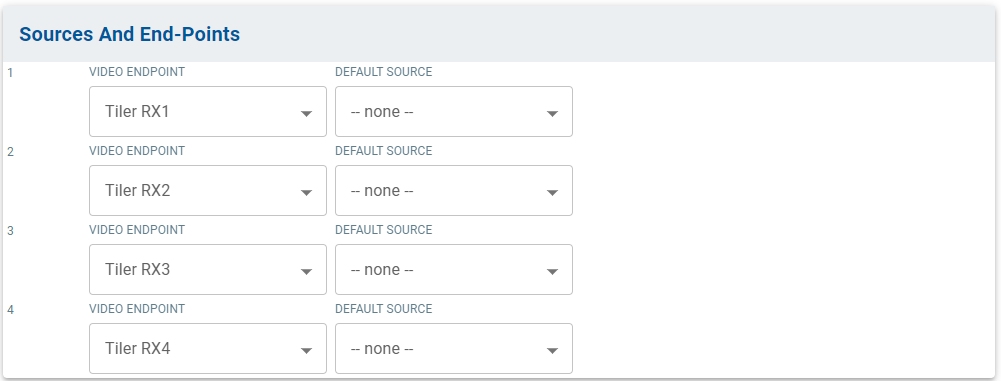
- Set Sources And End-Points to the four Tiler Receivers in the Tiling Room. Be sure to keep them in the same order as they are on the Report File and Room Connections. For Default Source, if you want a consistent source layout when the user selects the Tiler, set the sources here (We leave ours at --none--).
- Click Save, then return to the Dashboard.
- Select the Presets tab. Click Add Preset to create new Presets. You will need one Preset per Tiling layout. (We will demonstrate four layouts.)
- Name them according to the layouts you are going to use. (We use Quad, Primary Left, Primary Top, Picture-in-Picture.)
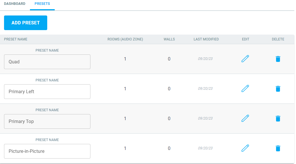
- Name them according to the layouts you are going to use. (We use Quad, Primary Left, Primary Top, Picture-in-Picture.)
- Click the Edit Pencil next to the first layout
- Check the box to enable the Preset
- Set the Audio Source if you want audio to change to a specific source when this preset is chosen. (We do not set an Audio Source.)
- Set Sources for each Video Endpoint when this Preset is chosen. Think of these as default sources when the layout is selected. (We set ours so that each window shows a different source. We only have 4 sources, so it is an easy choice.)
- Click Save, then go back to Presets.
- Repeat Step 5 for each Preset: Check the box, set audio and video sources, then Save.
- Agents and MultiDisplay Manager are done!
Part 3: Programming Macros
All of the buttons and interfaces exist. Now we need to make them do stuff!
- Under the Programming tab in Composer, scroll down to the MultiDisplay Manager.
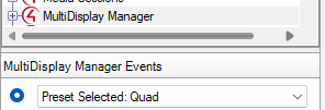
- Select the first Preset. (Ours is Quad.)
- On the Actions bar, select the Tiler TX driver in the equipment room - configured to control Tiling layouts - and scroll down to Device Specific Command.
- Select Console Command (Advanced) from the dropdown
- Copy+paste the layout command for Quad: _4in1_layout.sh 4. (All 759A layout commands can be found here). Refer to step 5 for MC-QX commands.
- Drag the green arrow into the Script Actions window
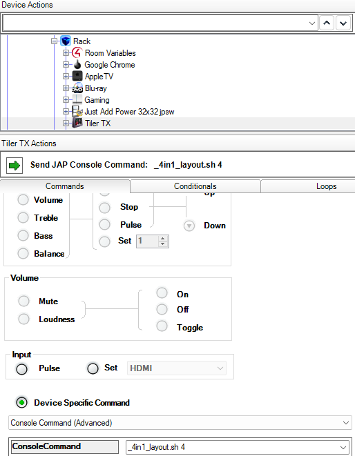
- Primary Left and Primary Top are done in the same way as Step 2, with only the 4 changing to a different number. Refer to step 5 for MC-QX commands.
- Picture-in-Picture is done in the same way as Step 2, but the command is longer. Refer to step 5 for MC-QX commands.

- If the MC-QX is being used rather than the 759A, please refer to our MaxColor Tiling API for all command functions.
- Programming Macros is done!
Part 4: Refresh Navigators and Go!
Programming is complete and the MultiDisplay Manager is setup to control the Tiling Transmitter. Refresh Navigators to update the UI.
- Select a Room to watch the Tiler Source
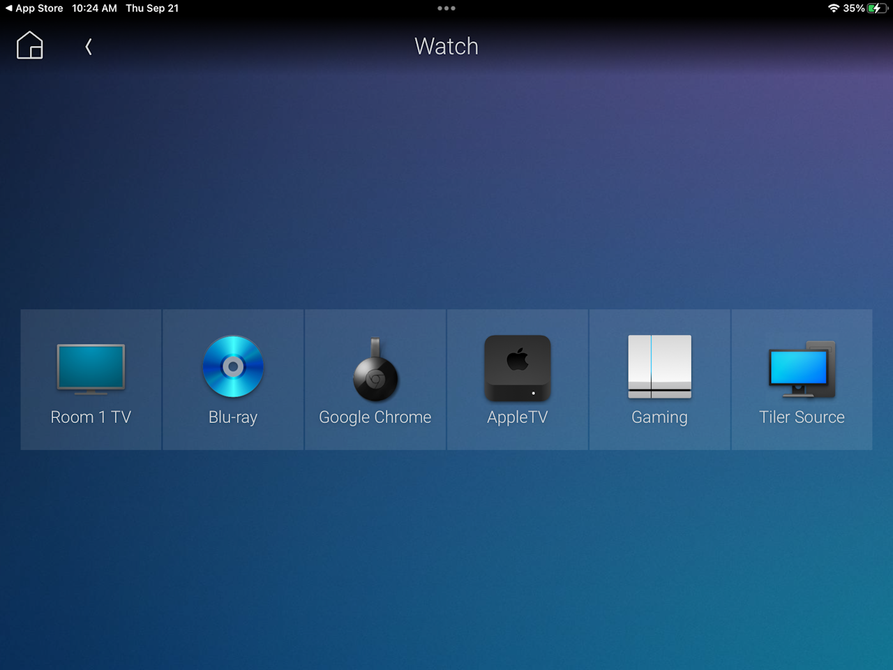
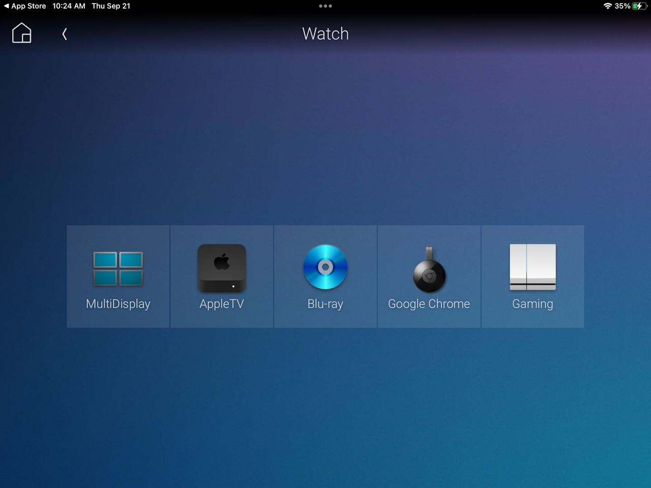
- Select the Tiling Room and select MultiDisplay Manager
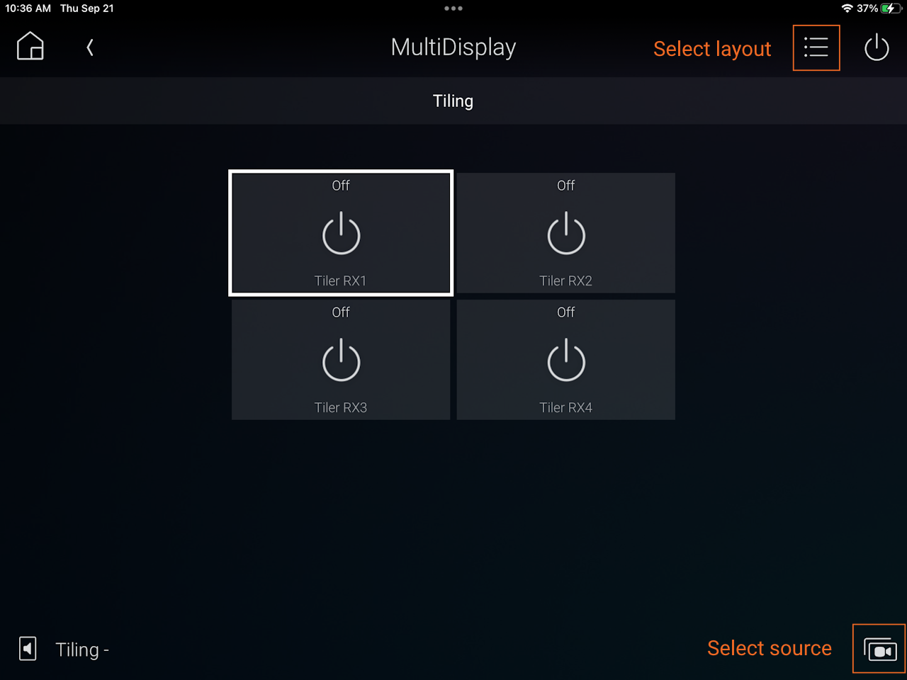
- Set sources by selecting a window then selecting the source button in the bottom-right corner
- Set layout by selecting the list menu in the top-right corner
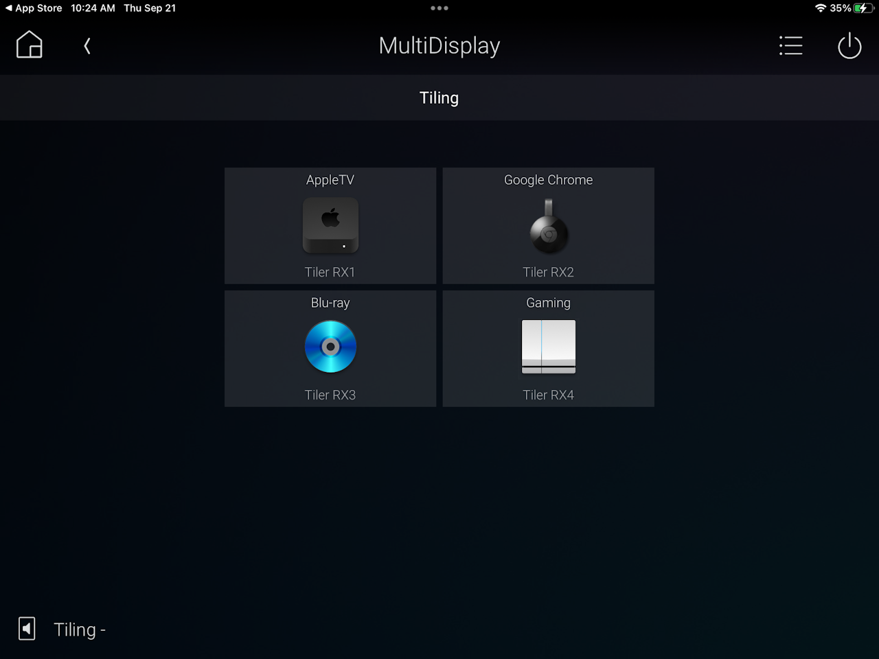
- The Room is now displaying the Tiling Encoder. All other Rooms can also watch the Tiler at the same time, with the same layout and sources. Done!
Download - Control4 Driver for AMP Standardized Systems
Overview
This driver package is for Just Add Power Omega, Ultra, and MaxColor systems configured as a Standardized AMP system - through the Let's Go option.
The included drivers provide Matrix Control, Endpoint Control, and Feature Control.
- Matrix Control - switch any display to watch any source
- Endpoint Control - manage sources and displays with IR, RS232, or CEC
- Feature Control - manage features of Just Add Power like video wall, image pull, tiling control
Driver supports up to 101 inputs and 128 outputs.
Potential for up to 3000 outputs, but larger potential driver sizes impact Composer performance. Reach out to support if you need more than 128 outputs.
Contracted by Just Add Power.
This driver is NOT COMPATIBLE with systems configured with JADConfig.
Download
Control4 Standardized AMP Driver
Basic Driver Setup
The steps below will be easier to accomplish if you have the AMP Report File on-hand. This file was generated when the system was initially configured by AMP, and can be found on the PC that ran AMP.
Switching Driver - avswitch_ip_justaddpower_jpsw.c4z
- Apply the Static Route to the router so that data network devices (aka the Control4 processor) can communicate with Just Add Power devices on their subnet.
- Load one driver into the Control4 project. There are many driver sizes, listing the maximum size of the system; choose a size that fits the system.
- In Connections --> Network tab, enter the IP address of any active Just Add Power Decoder or Encoder - we recommend the first Decoder: 172.27.1.1
- In Connections --> Control/AV tab, use the Report File to connect Decoder 1 to Output 1, Decoder 2 to Output 3, etc. Connect Encoder 1 to Input 1, Encoder 2 to Input 2, etc.
- In System Design, selecting the driver will show the Status as Operational - {#Encoders}x{#Decoders}x{#Switches}. For example, Operational - 10x13/1
Endpoint and Feature Control Driver - proxy_ip_JustAddPower_TerminalServer.c4z
- Apply the Static Route to the router so that data network devices (aka the Control4 processor) can communicate with Just Add Power devices on their subnet.
- Load one driver per endpoint into the Control4 project - an endpoint is a Decoder or Encoder - that will be control RS232/IR/CEC/Video Wall/Tiling/etc
- In System Design, enter the IP address of the target Decoder/Encoder in the IP Address field
- If using IR or Serial control, set the appropriate settings
Video Guide
Your browser does not support iframe.
Your browser does not support iframe.
Versions
- avswitch_ip_justaddpower_jpsw.c4z - switching driver v002
- Various sizes available from 8x8 to 128x128.
- Driver sizes represent maximum sizing and will support any smaller system
- Includes a backup controller IP in case the primary controller IP drops offline
- proxy_ip_JustAddPower_TerminalServer.c4z - Just Add Power Endpoint and Feature Control driver v3.02
- Behaves like a display in Composer with an HDMI input, serial output, IR output, and CEC power on and off commands
Switching Multiple Displays
The Matrix Control driver gives the ability to switch multiple outputs simultaneously using a device- specific command from the Programming tab in Composer.
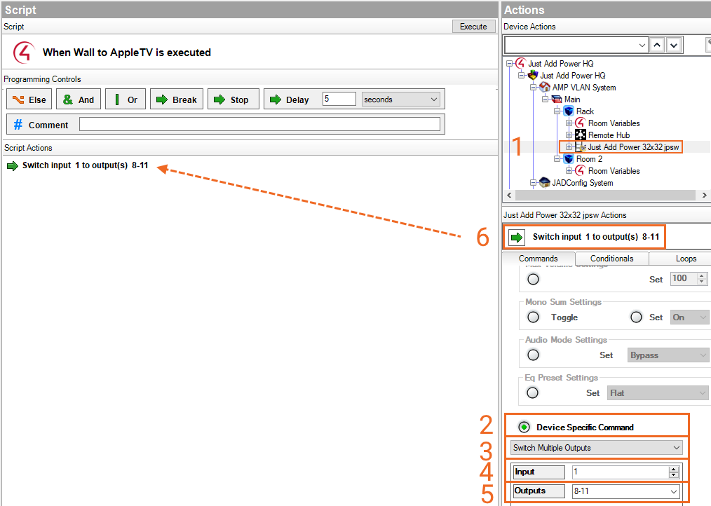
- In Actions, select the Matrix Control driver
- Scroll down to Device Specific Command
- Select Switch Multiple outputs from the dropdown
- Set the Input value to the Transmitter number of the source to switch to (from the Report File)
- Set an Output range by listing Receiver numbers that will switch (from the Report File)
- Drag the command into the Script window
Changes
- proxy_ip_JustAddPower_TerminalServer.c4z
- Updates Serial over IP options: Serial, IRv1, IRv2, MaxColor IR
Other Drivers
For drivers compatible with JADConfig, go to Control4 JADConfig Driver Download.
Setup Endpoint Control (RS232, IR, CEC) for Encoders & Decoders
Overview
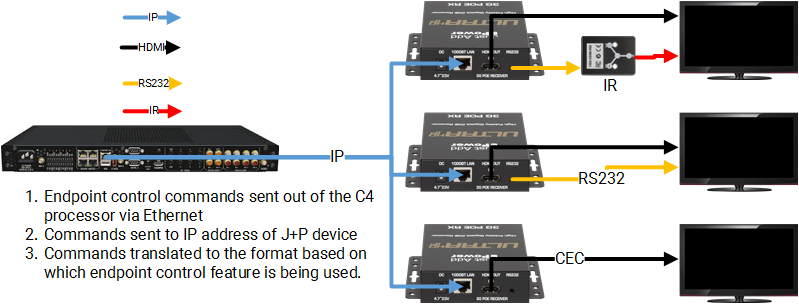
Control4 systems can use Just Add Power Encoders and Decoders as an extension cord to manage sources and displays through CEC, IR, or RS232.
Control is done on an individual device basis, so you can have a mixture of CEC, IR, and RS232 control in the same system depending on the needs of the endpoint.
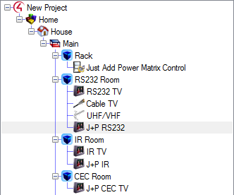
IP control is also possible in a Just Add Power system, but Just Add Power is not part of the communication pathway for IP control.
Requirements
- Just Add Power devices running the latest firmware.
- One Terminal Server loaded for each endpoint.
- A Static Route on the router connected to the system so the Control4 processor on the Data network can communicate with the Just Add Power network
- RS232 is supported on all Just Add Power devices.
- IR is supported on all devices, but requires the Flux Capacitor IR Dongle. Review the Setup Guide for the Flux Capacitor IR Dongle to ensure the proper physical setup and connectivity of the Flux Capacitor before beginning.
- CEC is supported on:
- 2G+ Series
- Omega Series
- Ultra Series
- MaxColor Series
Setup RS232
- Load the appropriate display or source device into your Control4 project that you wish to control over RS232. Ensure that the device has an RS232 Input connection. Bind the HDMI connection of the endpoint driver to the matching HDMI Input or Output on the Just Add Power Matrix Control driver. The display driver will be the audio and video endpoints for the room.
- Load a Just Add Power RS232-IP Server. It will look like a display inside Composer.
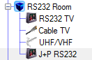
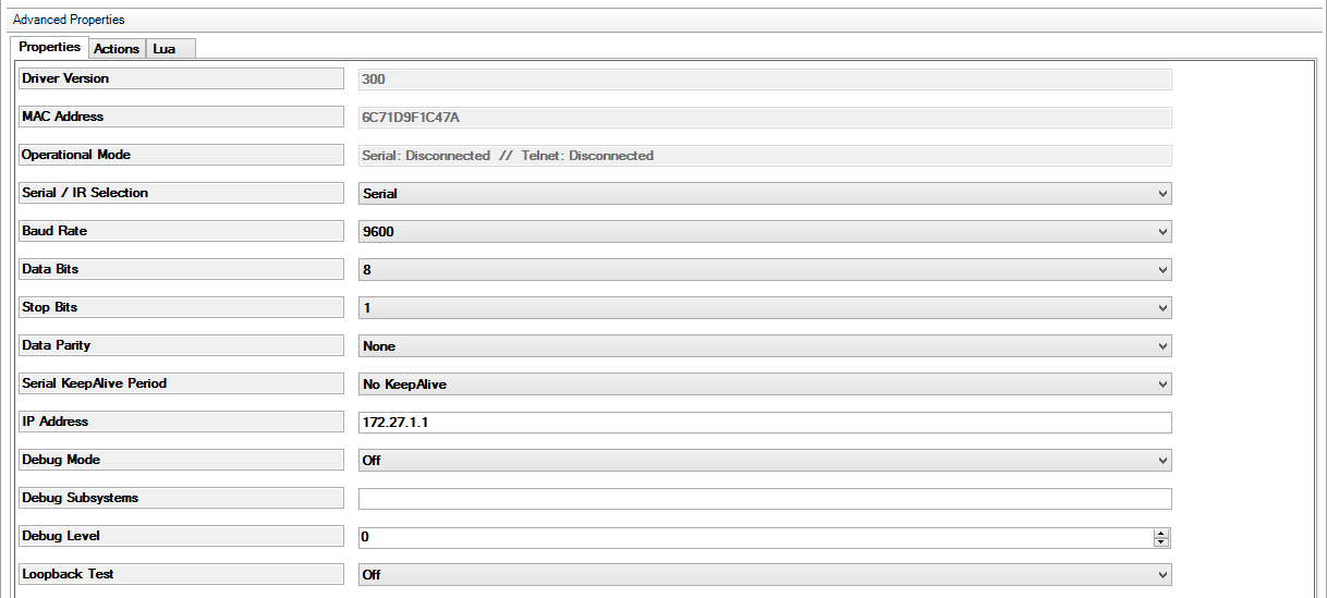
- In the RS232-IP Server driver properties, set Serial/IR Selection to Serial. Set the Baud Rate to match the baud rate of the endpoint device. Set the IP Address to the IP of the Encoder or Decoder connected to the endpoint device.
- In System Design, connect the RS_232 Output of the RS232-IP Server to the RS232 Input of the endpoint driver. Remember, the HDMI connection is already made between the endpoint driver and the Just Add Power Matrix Control driver. The RS232-IP Server driver WILL NOT have an HDMI connection.
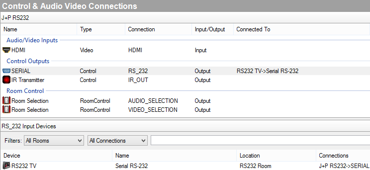
- Done! Commands from the RS232 endpoint driver will be passed over IP to Just Add Power, which will convert it to serial to control the endpoint device.
Setup IR
- Load the appropriate display or source device into your Control4 project that you wish to control over IR. Ensure that the device has an IR Input connection. Bind the HDMI connection of the endpoint driver to the matching HDMI Input or Output on the Just Add Power Matrix Control driver. The display driver will be the audio and video endpoints for the room.
- Load a Just Add Power RS232-IP Server. It will look like a display inside Composer.

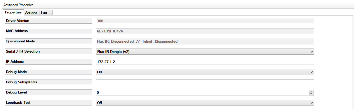
- In the RS232-IP Server driver properties, set Serial/IR Selection to Flux IR Dongle (v1) or (v2) based on the dongle version you have. Go here if you're not sure which version you have. Set the IP Address to the IP of the Encoder or Decoder connected to the Flux IR Dongle.
- In System Design, connect the IR_OUT of the RS232-IP Server to the IR Input of the endpoint driver. Remember, the HDMI connection is already made between the endpoint driver and the Just Add Power Matrix Control driver. The RS232-IP Server driver WILL NOT have an HDMI connection.
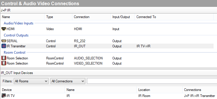
- Done! Commands from the IR endpoint driver will be passed over IP to Just Add Power, which will convert it to IR to control the endpoint device.
Setup CEC
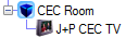
- Load a Just Add Power RS232-IP Server. It will look like a display inside Composer. DO NOT load a driver for the display itself.
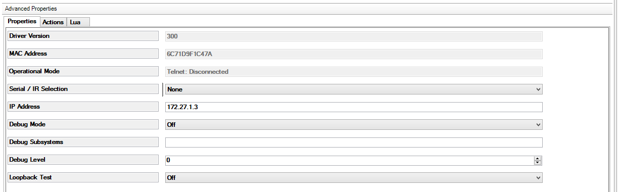
- In the RS232-IP Server driver properties, set Serial/IR Selection to None. Set the IP Address to the IP of the Encoder or Decoder connected to the endpoint device.
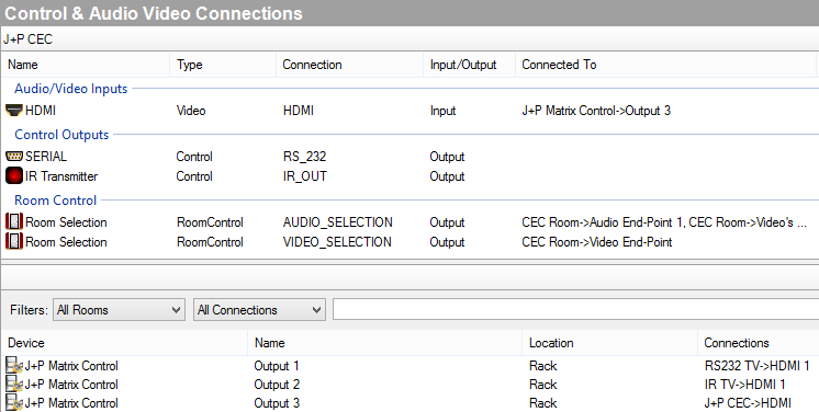
- In System Design, connect the HDMI Input of the RS232-IP Server to the correct Output of the Just Add Power Matrix Control driver (Output 3 in the image). CEC commands are sent over the HDMI cable so no other connection is needed. This will make the RS232-IP Server the video and audio endpoint for the room.
- Done! CEC commands will send over IP to Just Add Power, which will convert it to CEC to control the display.
- CEC only supports 3 functions: Power On, Power Off, and Select HDMI 1. If you need to control additional functions, you must use another control method.
CEC Programming with Samsung Displays
Samsung Displays need an additional step performed in Control4 in order control them with CEC because they do not respond unless prefaced by a HDMI Select command prior to sending an On or Off command.
***DO NOT start without first following the instructions found in Setup CEC.***
- Add the Room Control Driver to every room that will have a Samsung Display.
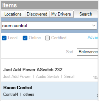
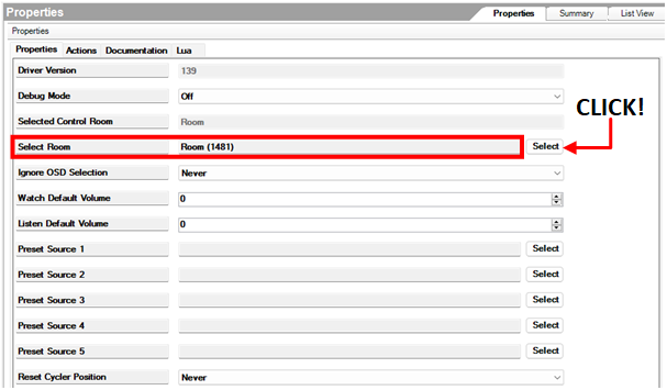
- Navigate to System Design and select the Room Control Driver.
- Under "Select Room" choose the room in the dropdown reserved for the Samsung Display.
- Navigate to Programming and under Device Events select the Room Control Driver that you loaded into the project.
- Select the dropdown on the left-hand side of Composer and choose Room Turned On.
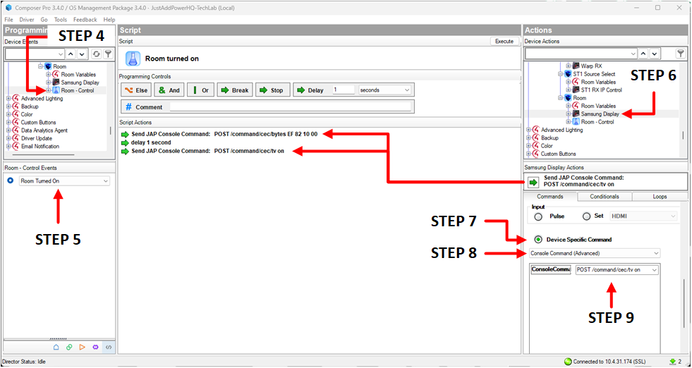
- Under Actions on the right-hand side of Composer, scroll down and select the RS232-IP Server Driver.
- Once you have selected the RS232-IP Server Driver, below under Control Actions, scroll down until you find Device Specific Command and check the bubble to enable it.
- Under Device Specific Command is a drop down. Select Console Command (Advanced)
- In the string box write and add the following commands to the Script Actions:
- POST /command/cec/bytes EF 82 10 00
- POST /command/cec/tv on
- Add a delay between the commands as needed.
- Navigate back to Device Events on the left side of Composer and select Room Control Driver again.
- Select the dropdown on the left-hand side of Composer and choose Room Turned On.
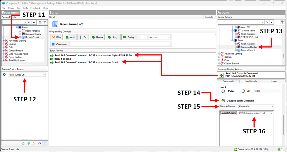
- Under Actions on the right-hand side of Composer, scroll down and select the RS232-IP Server Driver.
- Once you have selected the RS232-IP Server Driver, below under Control Actions, scroll down until you find Device Specific Command and check the bubble to enable it.
- Under Device Specific Command is a drop-down. Select Console Command (Advanced)
- In the string box write and add the following commands to the Script Actions:
- POST /command/cec/bytes EF 82 10 00
- POST /command/cec/tv off
- Add a delay between the commands as needed.
Setup a Video Wall with Control4's MultiDisplay Manager
Overview
The instructions in this article will use the MultiDisplay Manager to program an interface for a Just Add Power Standard Video Wall.
Before beginning this article, it is expected that you have:
- Configured all Just Add Power devices
- Configured the switching driver by connecting other sources and displays
- Added all non-Just Add Power drivers to the Composer project
- Configured initial video wall positioning through the webUI of a Just Add Power device: Ultra Series or MaxColor Series instructions.
In Control4 Composer OS3, a video wall is represented by one Just Add Power RS232-IP Server per display.
Latest Control4 drivers available here.
Note: As of Composer 3.4.0, MultiDisplay Manager is not available on many iPhones.
Training Video
If you would rather watch a training video:
Your browser does not support iframe.
2x2 Video Wall Template
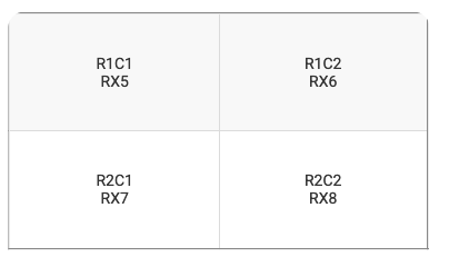
We will setup a 2x2 video wall. MultiDisplay Manager supports up to 3 rows and 6 columns, so these instructions can be replicated for walls up to that size.
Part 1: Add Room and Drivers
- Create a new Room (we name ours Video Wall)
- Add drivers for the displays in the wall. These are used for control of the displays and AV connections. Treat this step like adding any other display to a normal Room.
- In Control/AV Connections, connect each display driver to the Just Add Power Switching Driver Output according to the Report File. It is important that the display driver is connected, and not the Just Add Power RS232-IP Server drivers.
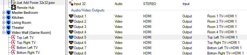
- In Control/AV Connections, select the Video Wall room. The first display added to the room is already the Video End-Point for the room. Connect the other 3 displays as Additional Video End-Points. This makes these displays available to the MultiDisplay Manager.
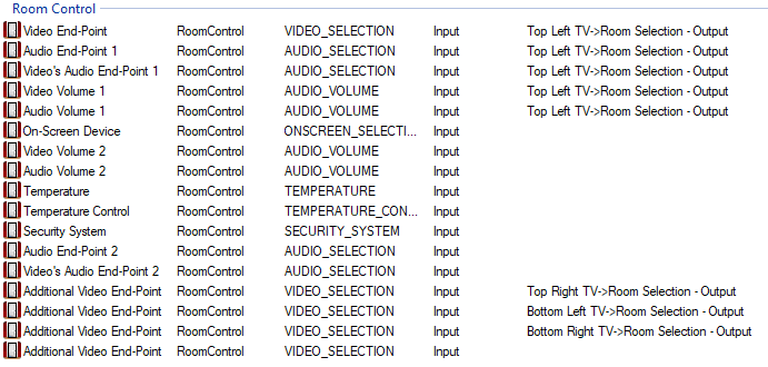
- These drivers are done!
- In Control/AV Connections, connect each display driver to the Just Add Power Switching Driver Output according to the Report File. It is important that the display driver is connected, and not the Just Add Power RS232-IP Server drivers.
- Add 4 Just Add Power RS232-IP Server drivers to the Video Wall room. These represent the four Just Add Power Receivers behind the video wall (We name ours Top Left, Top Right, Bottom Left, Bottom Right J+P)
- In Properties for each driver, set the IP address for each Decoder according to the Report File.

- These drivers are done! No Control/AV connections are needed.
- In Properties for each driver, set the IP address for each Decoder according to the Report File.
- Room, Drivers, and Connections are done!
Part 2: Agents and MultiDisplay Manager
Now that all Connections are made, the MultiDisplay Manager allows the user interface to control more than one display in the same room.
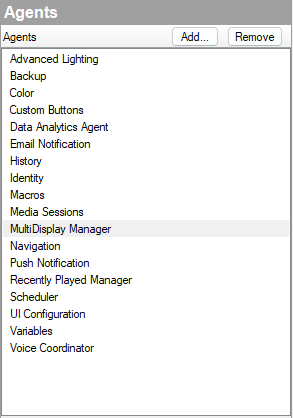
- Under Agents in Composer, click on Add, and add MultiDisplay Manager to the Agents window if not already there.
- In MultiDisplay Manager on the Dashboard tab, click Add Wall and set the Audio Zone (Room) to Video Wall.
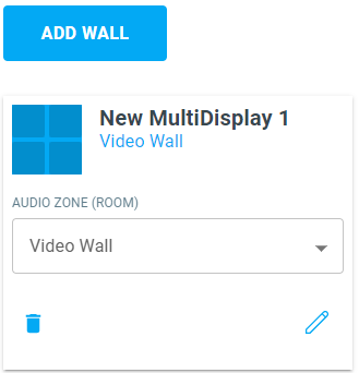
- Click the Pencil icon to configure the wall
- Set the Wall Name - this is how the user will see it on the interface. (We named ours 2x2 Video Wall)
- Set Audio Zone (Room) to the Tiling Room.
- Set the Audio Source to the audio source for the room (we leave our Audio Source blank because we are not doing audio).

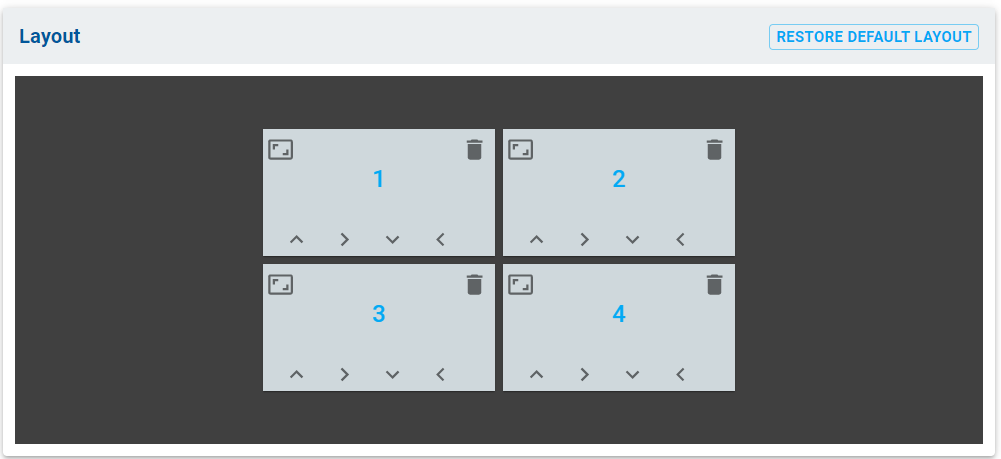
- Set Layout to 2 Rows and 2 Columns and click Get Started. The layout is how the user will see it on the interface. Resize as you like. (We leave ours at default.)
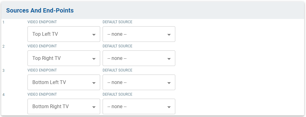
- Set Sources and End-Points for the displays in the wall. Be sure to keep them in the same order as they are on the Report File and Room Connections. For Default Source, if you want a consistent source layout when the user selects the wall, set the sources here. (We leave ours at --none--)
- Click Save, then return to the Dashboard.
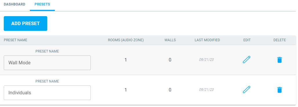
- Select the Presets tab. Click Add Preset to create two new Presets: one for Wall Mode, and one for Individual displays. This allows the user to change between one large wall and individual screens. (For larger walls, you may want more than two Presets for more layout options.)
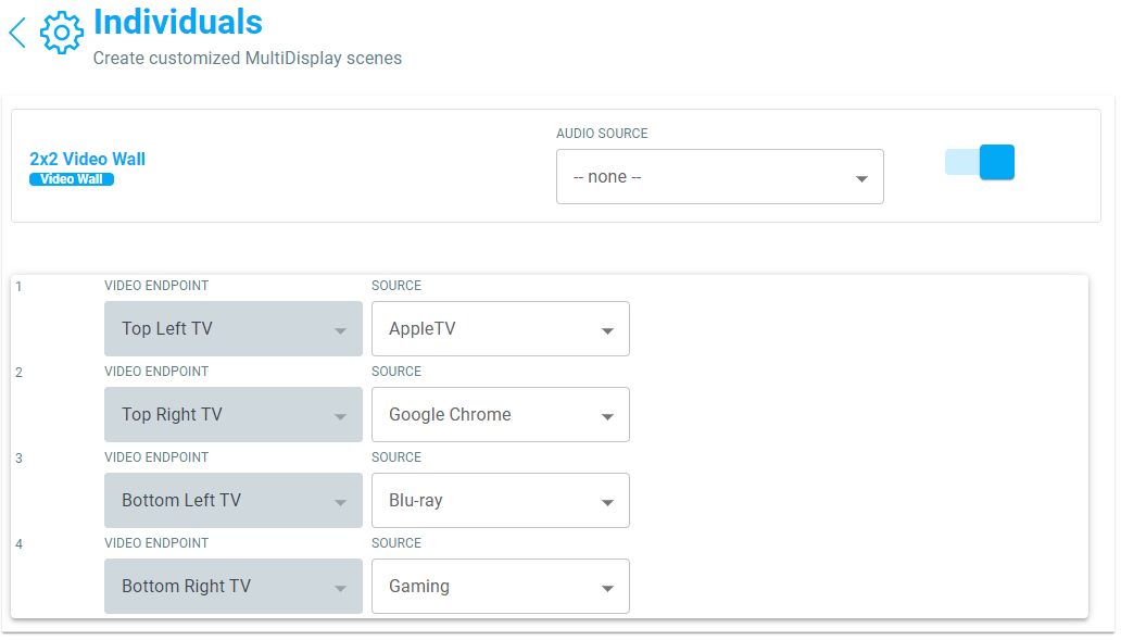
- Click the Edit Pencil for the Individual preset
- Check the box to enable the Preset
- Set the Audio Source if you want audio to change to a specific source when this Preset is chosen. (We do not use audio)
- Set Sources for each Video Endpoint when this Preset is chosen. Think of these as default sources when the layout is selected. (We set ours so that each window shows a different source. We only have 4 sources so it is an easy choice.)
- Click Save, then go back to Presets.
- Click the Edit Pencil for the Wall Mode preset
- Check the box to enable the Preset
- Set the Audio Source if you want audio to be on a specific source when this Preset is chosen. (We do not use audio)
- Set Sources for each Video Endpoint when this Preset is chosen. This of this as the default source when the layout is selected, and since it is a video wall all endpoints should be set to the same source. (We set ours to the AppleTV by default, as it is our most-used source. Fit this to your user's requirements.)
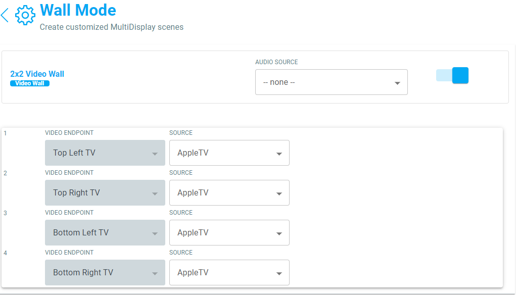
- Click Save, then go back to Presets
- Agents and MultiDisplay Manager are done!
Part 3: Programming Macros
All the buttons and interfaces exist. Now we need to make them do stuff!
- Under the Programming tab in Composer, scroll down to the MultiDisplay Manager
- Select the Wall Mode preset.
- To build a video wall, Control4 must set 2x2 wall mode and positioning on all Just Add Power RS232-IP Server drivers. We'll do each of the drivers one at a time.
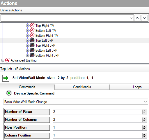
- On the Actions bar, select the Top Left J+P driver in the Video Wall room and scroll down to Device Specific Command.
- Select Basic Video Wall Mode Change from the dropdown
- Set Number of Rows to 2
- Set Number of Columns to 2
- Set Row Position to 1. This Decoder is in the first row of the video wall
- Set Column Position to 1. This Decoder is in the first column of the video wall
- Drag the green arrow into the Script Actions window
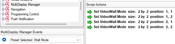
- Select the Top Right J+P driver and Basic Video Wall Mode Change
- Set Number of Rows to 2
- Set Number of Columns to 2
- Set Row Position to 1. This Decoder is in the first row of the video wall
- Set Column Position to 2. This Decoder is in the second column of the video wall
- Drag the green arrow into the Script Actions window
- Select the Bottom Left J+P driver and Basic Video Wall Mode Change
- Set Number of Rows to 2
- Set Number of Columns to 2
- Set Row Position to 2. This Decoder is in the second row of the video wall
- Set Column Position to 1. This Decoder is in the first column of the video wall
- Drag the green arrow into the Script Actions window
- Select the Bottom Right J+P driver and Basic Video Wall Mode Change
- Set Number of Rows to 2
- Set Number of Columns to 2
- Set Row Position to 2. This Decoder is in the second row of the video wall
- Set Column Position to 2. This Decoder is in the second column of the video wall
- Drag the green arrow into the Script Actions window
- The Wall Mode macro is built!
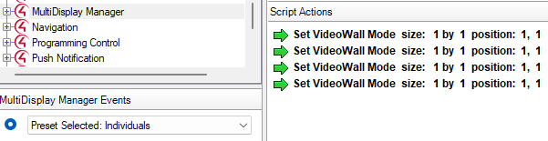
- Next we will build the macro for the Individuals preset to set the video wall to show 4 individual videos
- On the Actions bar, select the Top Left J+P driver in the Video Wall room and scroll down to Device Specific Command.
- Select Basic Video Wall Mode Change from the dropdown
- Set Number of Rows to 1
- Set Number of Columns to 1
- Set Row Position to 1
- Set Column Position to 1
- Drag the green arrow into the Script Actions window
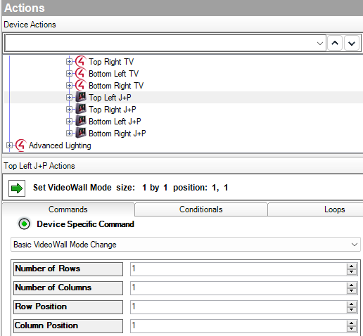
- Repeat Step 10 for each Receiver in the wall, setting Number of Rows, Number of Columns, Row Position, and Column Position to 1 for all values. Drag the arrow into the Script for each Receiver.
- Programming Macros is done!
Part 4: Refresh Navigators and Go!
Programming is complete and the MultiDisplay Manager is setup to control the video wall. Refresh Navigators to update the UI.
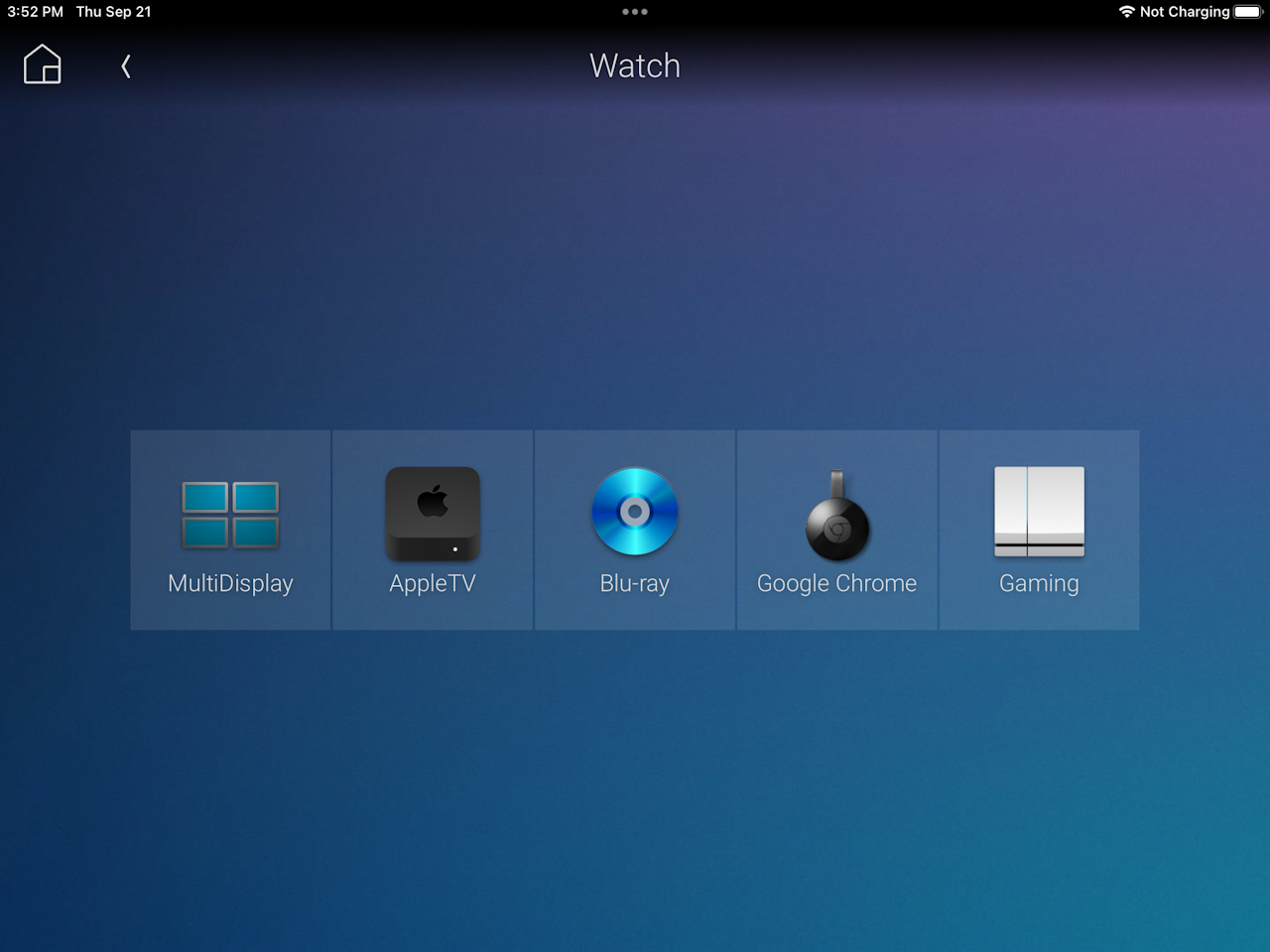
- Select the Video Wall room and the MultiDisplay Manager
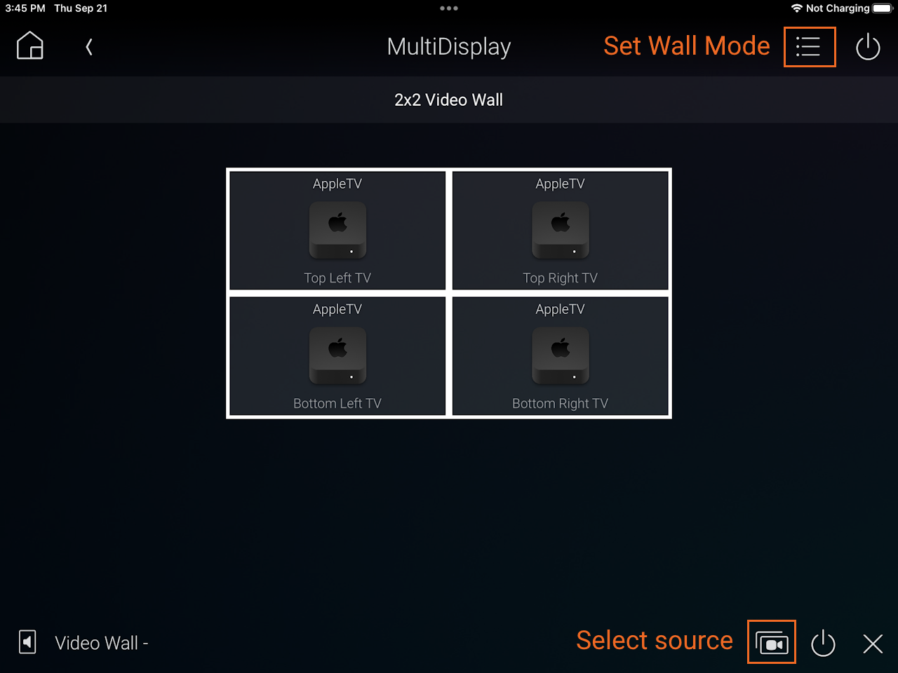
- To watch a video wall:
- Select the list menu in the top-right corner, then select the Wall Mode preset
- Select all displays in the wall, then select the source button in the bottom-right corner and pick a source to show on the wall
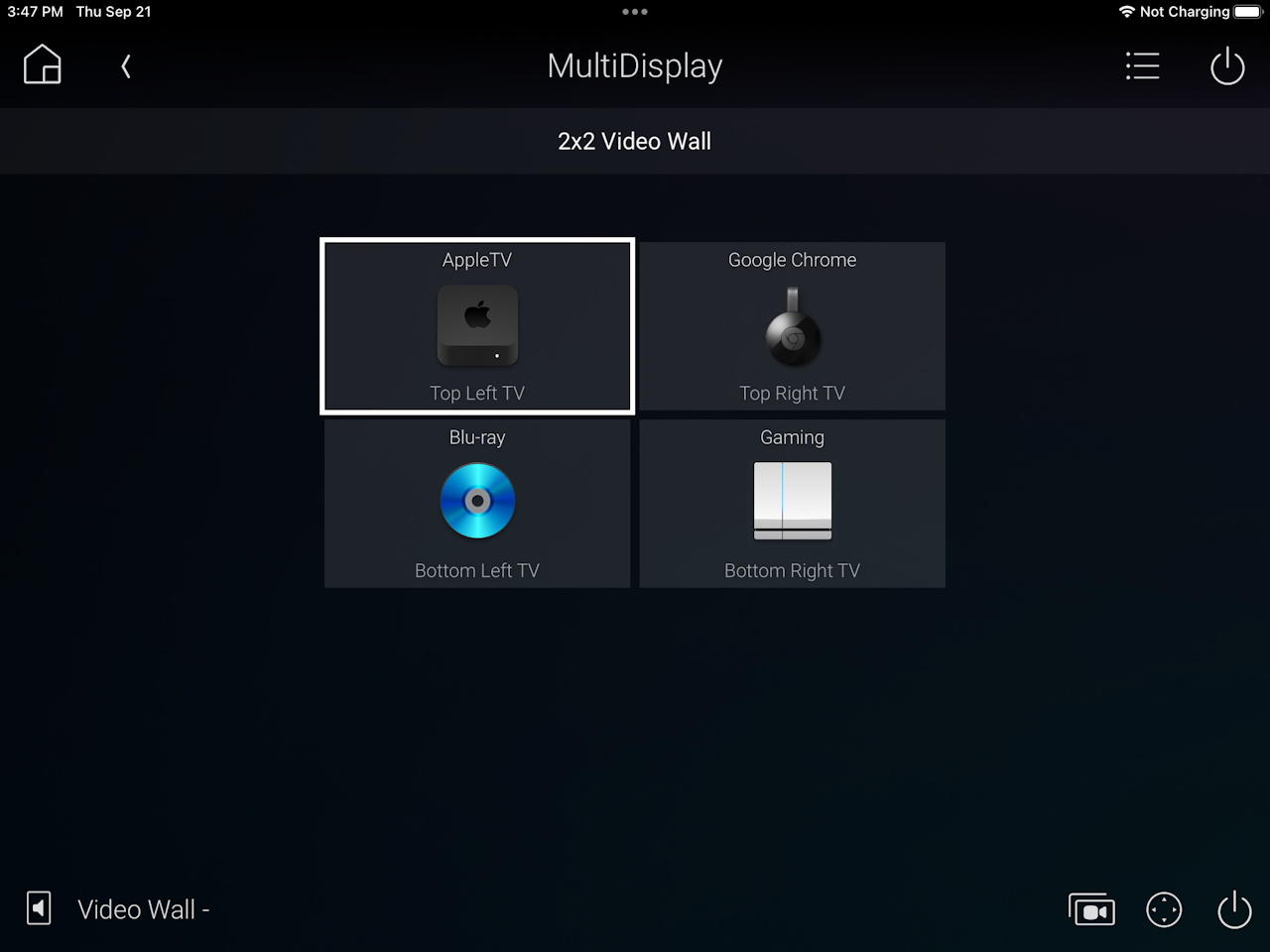
- To watch individual screens:
- Select the list menu in the top-right corner, then select the Individuals preset
- Select any display in the wall, then select the source button in the bottom-right corner to switch that display
- Done!
 AMX
AMX